Download
1 / 49
590 likes | 1.32k Views
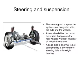
Steering Gear and Linkage. Steering. The steering system can be broken into two major components. The steering column and shaft All the components located in the passenger compartment The steering gear and linkage

E N D
Steering • The steering system can be broken into two major components. • The steering column and shaft • All the components located in the passenger compartment • The steering gear and linkage • The steering gear and linkage converts the rotary motion of the steering wheel into linear motion of the steering linkage • A set of gears is needed to accomplish this • Linkage is needed to connect the steering knuckles to the steering gear because the steering knuckles must move up and down with the suspension
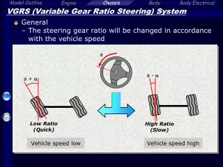
Steering ratio • The steering ratio is the number of turns of the steering wheel / number of turns of the steering knuckle. • Most passenger cars have a steering ratio of around 16 to 1. • 16 degrees of rotation of the steering wheel should produce 1 degree of rotation of the steering knuckle. 1o 1o 16o
Steering ratio • If the engine stalls or the power steering belt breaks the vehicle must be capable of being steered safely to a stop. • A lower steering ratio will have a quicker steering response but may make the vehicle nearly impossible to steer if the power assist fails. • The heavier weight applied to the front tires of a trucks calls for a steering ratio of 20 to 1 or higher.
Turns lock-to-lock • Most passenger cars have about 3 1/3 turns of steering lock-to-lock • If you turn the wheels all the way to the left until the steering will no longer turn and then count the number of rotations of the steering wheel can turn to the right until it reaches the steering lock – that is the number of turns lock-to-lock. • The average passenger car has about 3 and 1/3 turns. • Trucks usually have a higher number of turns due to their higher steering ratio, typically 4 ½ or more.
Steering stops • A steering stop is a mechanism in the steering linkage or steering gear that limits how far the steering knuckles can rotate. • Without steering stops the sidewalls of the tires will contact the fenders, frame or control arms. • On some suspension systems there are adjustable bolts on the control arms that contact a tab on the steering knuckle at full lock.
Steering stops • On most modern cars the steering stop is built into the steering gear. • If the steering linkage is serviced improperly it may be possible for the steering to turn 35 degrees to the right and only 25 degrees to the left. • If this was the case the tires may be damaged when making a hard turn as the steering angle exceeds the design limits.
Types of steering gear • There are two types of steering gear used on modern cars: • Rack and Pinion • Used on the majority of passenger cars • Re-circulating Ball steering box • Used on mostly on trucks • Sometimes called linkage steering
Rack and pinion steering Steering knuckle Steering arm • Rack and pinion steering is very compact and simple and has relatively few moving parts. • Steering arms can be extensions of the steering knuckle or separate parts that bolt to the steering knuckle. Rack housing Tie rod Tie rod Sub-frame Steering coupler
Linkage type steering Steering arm • Linkage type steering is often called a parallelogram linkage because the angles formed by the links produces a parallelogram. • With the steering straight ahead the linkage forms a rectangle. Tie rod Tie rod Steering knuckle Center link Pitman arm Frame Idler arm Recirculating ball steering box
Linkage [parallelogram] type steering Steering arm • When the steering is turned to the left or right the shape formed by the idler arm, pitman arm and center link changes to a parallelogram. Tie rod Steering knuckle Tie rod Center link Frame Idler arm Pitman arm Recirculating ball steering box
Rack and pinion vs. linkage steering • Rack and pinion steering is preferred by most drivers due to its positive feedback. • Since the rack must be located within a foot of the front wheel axis centerline it is difficult to install in rear drive vehicles where the engine is placed between the front wheels. • Some luxury car manufactures prefer to use recirculating ball steering because it isolates the driver from road shock transmitted through the steering.
Rack and Pinion location • Rack and pinion steering can be used on this sports car because the engine is located behind the front axle centerline.
Rack and pinion steering • On a front wheel drive car with the engine mounted transversely the steering rack can be mounted on the sub-frame directly behind the engine/transaxle.
Rack and pinion • Rack and pinion steering is very simple and has few moving parts. • When the pinion gear rotates the rack moves laterally. • The pinion gear is connected to the steering wheel – the rack is connected to the steering knuckles. Pinion gear Rack
Rack and pinion steering linkage Pinion shaft • The rack and pinion gears are mounted in an aluminum housing that usually sits on top of the front sub-frame. • Tie rods connect the each end of the rack to the steering knuckles. • The rack and inner tie rod ends are protected by rubber bellows. Rack Housing Tie rod Bellows Mount bushings Tie rod
Rack and pinion steering Pinion bearings Pinion shaft • The rack and pinion gears are located inside an aluminum housing that is bolted to the frame or firewall. • The rack is free to slide laterally on bores machined into the housing. • The pinion gear shaft is supported on ball bearings at the top and bottom. Rack bearing
Rack and pinion steering Bellows Inner tie rod end • The housing is filled with lubricating oil. • Seals on the ends of the housing and pinion shaft keep the fluid from leaking out. • Rubber bellows protect the ends of the rack and inner tie rod ends from dirt and moisture damage. Pinion shaft seal Rack Seal Rack Seal Air pressure equalization passage
Rack and pinion steering Bellows • An air passage connects the left and right bellows. • Without the air passage the bellows would collapse on one side and balloon on the other as the vehicle is steered Air pressure equalization passage
Tie rods Garter spring • Tie rods connect the steering gear to the steering knuckles. • The length of tie rods must be adjustable so that the toe angle for each wheel can be adjusted. • Tie rod ends are ball and socket joints similar to ball joints. • The tie rod ends must pivot with the steering and flex up and down with suspension movement. Nylon ball seat
Tie rods for rack and pinion steering • The tie rod assembly for rack and pinion steering has 3 components: • Outer tie rod end • Inner tie rod end • Jamb nut [lock nut] Outer tie rod end Jamb nut Inner tie rod end
Tie rod length adjustment Flats on tie rod • When the inner toe rod is rotated the assembly gets shorter, when it is rotated in the opposite direction it gets longer. • Most inner tie rods have machined flats to allow the tie rod to be turned using an open end wrench. Jamb nut
Recirculating ball • In the recirculating ball system the steering wheel is connected to a worm shaft. • The worm shaft is a screw that moves a nut. • Ball bearings located between the threads of the worm shaft and nut reduce friction to allow for a low steering effort by the driver. Nut Worm shaft Ball bearings Return tube
Recirculating ball Sector gear • As the worm shaft turn the balls thread there way to the end of the shaft. • A return tube transfers the balls back to the other end of the worm shaft. • The ball nut is in mesh with a sector gear. Nut Pitman arm Return tube
Recirculating ball • The teeth on the ball nut forces the sector gear to rotate. • The large end of the pitman arm is connected to the sector gear. • The small end of the pitman arm is connected to the steering linkage. Return tube
Steering linkage • Vehicle with independent front suspension have 5 links: Idler arm Pitman arm Center link Tie rod Tie rod
Housing What’s in the box. Nut Control valve Ball bearings Worm shaft Sector shaft AKA Pitman shaft
Ball nut and sector gear • Notice the center tooth is longer than the other two teeth. • This produces a variable steering ratio.
Sector shaft • Master spline allows the pitman arm to be installed in only four positions. • The spline at the bottom of the sector shaft is tapered to secure the pitman arm even if the nut loosens. Freeplay adjustment screw Seal surface
Sector [Pitman] shaft seal Master spline • The sector shaft seal is the most common problem with steering boxes.
Pitman arm • Some Pitman arms have an integrated ball and socket joint that connects the Pitman arm to the center link. • When the Pitman arm doesn’t have a ball and socket joint the joint is integrated into the center link.
Steering box is attached to the frame rail Freeplay adjustment screw • A flange on the side of the steering box is used to bolt it to the frame rail. • Steering boxes are designed to be mounted either ahead or behind the axle centerline. • If a steering box designed for forward mounting is installed a vehicle that requires a rear mounted box the steering will be backwards. [when you turn the steering wheel to the left the car will turn right] Mounting flange
Idler arm • The idle arm is attached to the passenger side frame rail and supports the center link. • Some idlers are two piece assemblies where the support bearing can be replaced separately from the arm and ball and socket joint. Bracket bolted to the frame Fixed pivot Ball and socket joint
Center link • Center links come in two varieties: • A solid steel bar with 4 holes • Rarely replaced because there’s nothing to wear out • A steel bar with 2 ball and socket joints and two holes
Tie rods on linkage steering systems Adjustment sleeve • The tie rods on linkage steering are 3 piece assemblies. • Inboard tie rod end with a ball and socket joint • A left hand thread is used to connect it to the adjustment sleeve • Outboard tie rod end with a ball and socket joint • A right hand thread is used to connect it to the adjustment sleeve • Adjustment sleeve forms the center of the assembly • The sleeve is tapped with internal left hand threads on one end and right hand threads on the other end Outboard tie rod end Inboard tie rod end
Steering linkage for solid axles Tie rod • A steering rod connects the pitman arm to the right side steering knuckle. • Four wheel drive trucks with live front axles use single tie rod to connect the steering knuckles. Frame Steering rod Pitman arm
Drag link steering Tie rod • In a drag link system the pitman arm is located outboard of the frame rail. Drag link Pitman arm • The drag link connects the pitman arm to the left side steering knuckle.
Drag link steering • This antique pickup truck has kingpins instead of ball joints for its steering pivots. Tie rod Drag link Steering arm Pitman arm
Toe • Toe is an alignment angle established by the length of the tie rods. • Toe is the difference in distance between the two front tires measured at the front [leading edge]and rear [trailing edge]. • Toe is normally expressed in inches but can also be expressed in millimeters or degrees. 59 7/8” 60 1/8”
Toe-in • When the tires are closer at the front the condition is called toe-in. • Toe-in is normally displayed on an alignment machine precede by a negative sign [-]. 59 7/8” - ¼” toe-in 60 1/8”
Toe-out • When the tires are closer at the rear the condition is called toe-out. • Toe-out is normally displayed on an alignment machine precede by a positive sign [+]. 60 1/8” + ¼” toe-out 59 7/8”
Zero toe 60” • When the vehicle is driven straight ahead at highway speeds the tires should be at zero toe. • Most cars and trucks are aligned for a small amount of toe-in to compensate for compliance in the control arm bushings. • The forces caused by positive scrub radius causes the tire to want to toe-out as the vehicle comes up to speed. 60”
Toe change during jounce/rebound • As the out board end of the tie rod moves up and down with the suspension it swings through an arc. • As the tie rod swings up and down during jounce/rebound the tire is pulled toward toe-in if the steering arms are located in front of the axle centerline.
Toe change during rebound • The location of the steering arm relative to the axle centerline determines whether the tire is pulled into toe-in or toe-out during jounce and rebound. • If the tie rods attach to the steering knuckle behind the axle centerline the tires will toe-out during jounce and rebound.
Bump steer • If both tie rods are the same length the toe change will be equal on both sides and the vehicle will not pull. • If one tie rod is longer then the car will momentarily pull to the side with the shorter tie rod when ever the tires encounter a bump. ¼” toe change ½ ” toe change 10.5” 9.5”
Bump Steer • The tie rods should be horizontal when the vehicle is at its static height. • If one side of the center link is higher or lower than the other side the car will bump steer to that side. • This condition is usually the result of an improperly installed idle arm.