Download
1 / 30
410 likes | 1.13k Views
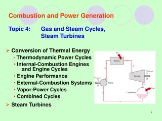
Lecture 8 – Axial turbines 2 + radial compressors 2. Axial turbines Turbine stress considerations The cooled turbine Simplified 3D axisymmetric inviscid flow Free vortex design method Radial compressors 2 Diffuser and vaneless space Compressor maps.

E N D
Lecture 8 – Axial turbines 2 + radial compressors 2 Axial turbines Turbine stress considerations The cooled turbine Simplified 3D axisymmetric inviscid flow Free vortex design method Radial compressors 2 Diffuser and vaneless space Compressor maps
Choice of blade profile, pitch and chord Annulus area Rotor blade stresses: • centrifugal stress: • gas bending stresses reduce as cube of chord: • centrifugal bending stress Source for fatigue failure Combination steady/fluctuating Steady stress/Creep
The cooled turbine • Cooled turbine • application of coolant to the nozzle and rotor blades (disc and blade roots have always been cooled). This may reduce blade temperatures with 200-300 K. • blades are either: • cast - conventional, directionally solidified, single crystal blade • forged
The cooled turbine Typical cooling distribution for stage: Distribution required for operation at 1500 K
The cooled turbine - methods Techniques to cool rotor blade • Air cooling is divided into the following methods • external cooling • Film cooling • Transpiration cooling • internal cooling
The cooled turbine - methods • Stator cooling • Jet impingement cools the hot leading edge surface of the blade. • Spent air leave through slots in the blade surface or in the trailing edge Techniques to cool stator blade
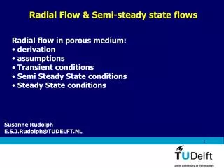
3D axi-symmetric flow (inviscid) • Allow radial velocity components. • Derive relation in radial direction • Balance inertia, FI, and pressure forces (viscous forces are neglected) • Derived results can be used to interpret results from CFD andmeasurements
3D flow (inviscid) • Pressure forces FP balancing the inertia forces in the radial direction are: • Equating pressure forces and inertia forces yields:
3D flow • For many design situations rs can beassumed to be large and thus αs small.These approximations give the radial equilibrium equation: • The above equation will be usedto derive an energy relation.
3D flow • The stagnation enthalpy at any radius is (neglecting radial components): • The radial variation is therefore: • We have the thermodynamic relation: which produces:
3D flow • We now have: • If we neglect the radial variation of entropy we get the vortex energy equation:
Theory 8.1 – The free vortex design method Use: and design for: • constant specific work at all radii • maintain Ca constant across the annulus Thus Cwr must be kept constant to fulfill our design assumption. This condition is called the free vortex condition • Designs based on free vortex principle sometimes yields a marked variation of degree of reaction with radius
Design methods (Λ m = 0.50) • For low root tip ratios a high degreeof reaction is required in the mid to ensure positive reaction in the root Free vortex blading (n = -1)gives the lowest degree of reaction in the root region!
Free vortex design - turbines • We have shown that if we assume • constant specific work at all radii, i.e. h0 constant over annulus (dh0/dr=0) • maintain Ca constant across the annulus (dCa/dr=0) • We get • Cwr must then be kept constant to satisfy the radial equilibrium equation • Thus we have Cw r = Ca tanα r r = constant. But Ca constant => tanα r r = constant, which leads to the radial variations:
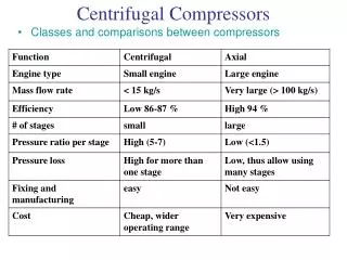
Radial compressor 2 - General characteristics Suitable for handling small volume flows Engines with mass flows in this range will have very small geometrical areas at the back of an axial compressor when operating at a pressure ratio of around 20. Typical for turboshaft or turboprop engines with output power below 10MW Axial compressor cross section area may only be one half or a third of the radial machine Better at resisting FOD (for instance bird strikes) Less susceptible to fouling (dirt deposits on blade causing performance degradation) Operate over wider range of mass flow at a particular speed
Development trends • Pressure ratios over 8 possible for one stage (in production – titanium alloys) • Efficiency has increased around % per year the last 20 years
The vaneless space - diffuser Use Cw and guessed Cr => C => T => M, Mr Perform check on area (stagnation properties constant):
Boundary layer growth and risk of separation makes stagnation process difficult Diffuser design will be a compromise between minimizing length and retaining attached flow The diffuser
Removes losses in clearance. Not used in gas turbines Add additional mass Unacceptable for high rotational speed where high stresses are produced Shrouds
We state that: Non-dimensional numbers - maps based on the observation that we can not think of any more variables on which P02 and ηc depends.
Nine independent parameters Four primary variables mass, length, time and temperature 9 - 4 = 5 independent non-dimensional parameters According to pi teorem. Non-dimensional parameters
Several ways to form non-dimensional numbers exist. The following is the most frequently used formulation: Non-dimensional numbers
For a given design and working fluid we obtain: Non-dimensional numbers Compressors normally operate at such high Reynolds numbers that they become independent of Re!!!
We arrive at the following expressions: Non-dimensional numbers Compressors normally operate at such high Reynolds numbers that they become independent of Re!!!
Data is usually collected in diagrams called compressor maps What is meant by surge What happens at right-hand extremities of rotational speed lines Compressor maps
What will happen in point D if mass flow drops infinitesimally Delivery pressure drops If pressure of air downstream of compressor does not drop quickly enough flow may reverse its direction Thus, onset of surge depends on characteristics of compressor and components downstream Surge can lead to mechanical failure Surge
What happens for increasing mass flow? Increasing mass flow Decreasing density Eventually M = 1 in some section in impeller (frequently throat of diffuser Choke
Overall turbine performance • Typical turbine map • Designed to choke in stator • Mass flow capacity becomes independent of rotational speed in choking condition • Variation in mass flow capacity below choking pressure ratio decreases with number of stages • Relatively large tolerance to incidence angle variation on profile and secondary losses give rise to limited variation in efficiency with rotational speed
Learning goals Have a basic understanding of how cooling is introduced in gas turbines Be familiar with the underlying theory and know what assumptions the radial equilibrium design principle is based on Have some knowledge about the use and development of radial compressor the physics governing the diffuser and vaneless space Understand what are the basis for compressor and turbine maps. Know about limitations inherent to the maps