Download
1 / 55
550 likes | 681 Views
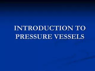
PRESSURE SYSTEM SEMINAR – PART 2 CEBAF CENTER L102/104 15 May 2009 9:30-11:00 A.M. Qweak Hydrogen Target System PS-TGT-08-001 Pressure System Lessons Learned. Dave Meekins and Ed Daly. System Overview. The system is a cryogenic liquid hydrogen target for Qweak experiment in Hall C.

E N D
PRESSURE SYSTEM SEMINAR – PART 2 CEBAF CENTER L102/104 15 May 2009 9:30-11:00 A.M.
Qweak Hydrogen Target SystemPS-TGT-08-001Pressure System Lessons Learned Dave Meekins and Ed Daly
System Overview • The system is a cryogenic liquid hydrogen target for Qweak experiment in Hall C. • System Fluids are H2 (target fluid) and He (CHL/ESR refrigerant). • Temperatures are low, 4K (He) and 20K liquid H2. JT valves Major Components Heat Exchanger Cell Pump Heater Hydrogen loop plumbing Hydrogen gas handling system (not shown) He refrigeration plumbing Instrumentation (not shown) Motion System Pump Heater Hx Loop plumbing Cell
How to Implement JLab Pressure Policies? • Some of the design and fabrication work started before January 2008. • What do we do with components under construction? • What policies do we have to comply with for new designs? • How do we treat the non standard components in the system? • Scheduling and budgetary constraints were applying pressure to continue with “business as usual”. • Asked the Pressure Committee for guidance.
Breakdown of the System • T=120 F MAWP=100psig • B31.3 and VIII D1 • T=-433F MAWP=100 psig • Code does not apply. Use equivalent measures and peer review. • T=-433F MAWP=100 psig • B31.3 • T=-453F MAWP=300 psig • VIII D1 STAMP REQUIRED • T=-453F MAWP=300 psig • B31.3 • Gas handling system Storage vessels (6000 gal) • Cell • Pump • Hydrogen loop plumbing • Heater • Heat Exchanger • Refrigeration Plumbing Temperature
Heat Exchanger • UA of HX was established to provide more than 2.5 kW at 20 K. • Designed in house and sent out for bids at 2 code shops. We provided the necessary code calculations (saved money). • Meyer Tool: Found design conflict with code. (UW-2b low temperature) • Eden Cryogenics: Lowest bidder but missed the error. • This caused procurement headache. • Statement of work: • Used the language “lowest price technically acceptable”. • Language using “Best value” would have made it easier to reject unsuitable vendor.
HX Head Modification Full penetration with integral backing Welds not full penetration UW2 requires full penetration welds for our case Interior structure not a pressure boundary Pressure boundary
Cell and Pump • The Codes do not apply. • Pump case and cell body are made from unlisted aluminum alloys. • Weld procedures are needed. • Design strength of welds are unknown. • WPS was developed and tested. Used lowest pull test values for design. • Using design basis in B31.3 for unlisted materials where possible. • More complex analysis was needed for non standard geometries. • FEA (VIII D2) • Reviewed hand calculations • Rely on testing for unlisted materials/geometries: • Pressure testing of components • B13.3 where possible • Use sound engineering judgment/peer review • Sensitive He leak check in reverse. • Thin cell apertures are being extensively tested. • No impact testing was performed.
Qweak Cell Exit window Entrance window e-
Entrance Window 0.004 in Burst pressure exceeded 500 psig
Hydrogen and Refrigeration Plumbing • This plumbing has been designed and fabricated to B31.3 • The Minimum Design Metal Temperature (MDMT) is -452 F. • There are non standard components in the system (Conflat flanges, unlisted materials…) • Parts of the system are contained in an large insulating vacuum vessel. • Parts of the system are already existing. • Expansion joints (flexible metal hose) were used to alleviate stress from temperature gradients, misalignments, seismic and other loads. A complex flexibility analysis can be simplified (B31.3 319.4). • How should seismic loads be quantified and treated?
Implications of low MDMT • B31.3 requires impact testing for SST304 at this temperature. • Tests are required for base metal, weld metal, and HAZ. • St Louis Testing Lab is capable of doing this. • Section VIII has 2 provisions which can be helpful. • UHA-51g allows for exemption from impact testing for low stress in high alloy steels. • B31.3 has a similar exemption but with a temperature limitation. • Div 1 and 2 have a provision that impact testing may be performed at 77K for SST304 when 316L welding rod is used with an F number less than 5. • B31.3 does not have such a provision. • Only components thick enough are required to be tested.
B31.3 Conflat (CF) Flanges • Conflat (CF) flanges have been used extensively in the past. • They provide a reliable seal at design temperature. • Allow for quick replacement and modification of system components. • Eliminate RadCon issues from welding/grinding/brazing. • B31.3 references VIII Appendix 2. • Flange bolt loads and gasket seating forces were measured for a variety of geometries and gasket materials. • Off the shelf CF flanges and bolts are not compliant with Appendix 2 (at least in a conservative analysis) when using standard copper gaskets. • MDC will supply COC but not CMTRs. • Flanges may not be made from bar stock (UG-14). • Bolt stress exceeds code allowable for SST.
Lessons Learned • Code may apply to some components and not others. Where the code does apply it must be used. • Use caution when writing statements of work to allow for changes and mistakes. • Low MDMT can lead to challenges • Charpy tests • Subtleties in the code • Unlisted materials can be useful but require some type of analysis/testing to determine design criteria. • Policy/guidance regarding seismic analysis would be useful.
CHL Oil Removal Relief RepairPS-CRY-08-015 Errol Yuksek 15 May 09
The Event • September ‘08 • Relief valve activated to keep pressure under control • Branch separation
Layout • Controller card failure GHe Storage Tanks Relief Oil Removal 4K Cold Box Compressors
Relief Valve • Set-point of 300 psi • Helium flow capacity 2.8 kg/s • Protects the CHL main compressor and oil removal systems • 20 ft elevation
Immediate Repair • Isolate the leak • Immediate repair crucial • Sound engineering judgment • Defer code analysis • Improve upon the repair if needed
Failed Installation Long outlet pipe - moment arm produces larger stress at base Inadequate reinforcement at base
Bench Test – verify relief set pressure Reduce the stresses Increase moment of inertia at the base Shorten relief outlet Add external support Gather materials on hand In-Process Examinations – qualified weld examiner (not welders) Leak Check – intermediate checks and final check at operating pressure Repair Process
Twice as much reinforcement was installed than required by B31.3 Branch Reinforcement Calculation
Stress Analysis of Old Installation Stress at Inlet 59 ksi > Yield Stress of 304L 25 ksi Stress after repair 33 ksi improvement required
Improved Installation Outlet Tee – momentum cancelling
Stress Analysis of New Installation P. Knudsen Stress at Inlet 3.7 ksi < Allowable Stress of 304L 16.7 ksi
Repair or Modification? • ESH&Q Ch. 6151 ¶6.8 Repairing or Modifying a Pressure System • “Repairs to piping systems shall be made using sound engineering principles.” • “Modifications to piping systems shall be made using current ASME Codes and/or documented equivalent measures.” • “Changing the service of a pressure vessel or piping system is also viewed as a modification. Changing the service can mean any change in the application or change in the location of the vessel or piping if the structural support is affected.” • Neither application or location were changed. • Interpreted as a repair of the piping system.
Stainless steel did not have certifications Spectrum analyzer Does not distinguish between 304 and 304L 304L assumed for conservative analysis (allowable stress of 16.7 ksi as opposed to 20 ksi). Material
Root Cause • October ’04 • Engineering change • No record of a walk-down • Lack of an established, controlled process for verification of engineering changes resulted in unchanged outlet pipe • Implementation of ESH&Q Chapter 6151 establishes multiple checks to prevent such occurrences 04’ Installation Drawing
Questions? • Many thanks to Dave Kashy, Ed Daly, and Michael Bevins for their assistance in the repair process.
DOE QA Program Review Kelly Dixon 15 May 09
P2 Findings • Four findings: • JSA Training Program not compliant • Corrective actions for DOE external assessment findings not adequately tracked and closed • Documents and record management not compliant with QA program for some JSA orgs • FIND-DES-P2-004
FIND-DES-P2-004 • PS records management • not compliant w/ ES&H Chapter 6151 • doesn’t ensure control between design specs, p. testing and final installation • extent of condition unknown
Reviewed Documents • Training records • Gas tank specification from another ongoing project • PS-CRY-08-008 (Docushare folders) • Design calculations • Traveler • Pressure test procedure and records • Drawings • DA completion statement • PS-CRY-08-012 folders • Design calculations • Pressure test records • Drawings
Basis for Finding • Specifically: • Drawing folder included an item that may not have been built • Modified item test records not in designated project folder (ESR 80K Bed U-Tube Mods) • Design documents not signed in file containing upgraded design • Signed DA completion statement states “system has been installed and in operating condition”
Basis for Finding (cont.) • Also noted: • Pressure test records not consistent where some are hand written • Wide range of content and formats within PS documents • Ch 6151 T1, titled “Pressure System Project Implementation and Documentation Guidance” imparts an advisory nature contrary to mandatory recordkeeping language
Lessons Learned • Maintain consistency in forms and process • Verify all completed items, no matter how simple they are • Ch 6151 T1, renamed to “Pressure System Project Implementation and Documentation Requirements”
Lessons Learned (cont.) • QA inspector must verify all documents • Ref Ch 6151 T1, ¶ 4.13 Final System Walkthrough: The QA representative shall perform the final safety walk-through for the pressure system before it can be released for operation. This effort shall include reviewing the Pressure System Checklist and DocuShare Folder for completeness, and ensuring that pressure system marking is consistent with applicable code requirements.
Pressure Systems, Chapter 6151 UpdatesPolicy Changes and Chapter Edits Will Oren for the Pressure Systems Committee May 15, 2009
Change/Enhancement Summary • Chapter 6151 • Pressure system definition • Identifying if you have a pressure system • Vessel stamping requirements • Vacuum vessels • Repairs & modifications • Appendix T1 • Guidance changed to requirements • Upfront peer review for “equivalent measures” • System inspection requirements • Appendix T2 – Scope section is changed • Appendix T3 – Foam windows • Appendix T5 – Vacuum Systems ** NEW**
Chapter 6151Changes • Section- “Key Terms” – Pressure System: 0 psig or greater unless all the following hold: • <15psig • Non-flammable/toxic per ASME 31.3 paragraph 300.2 • Temperature between -20˚ and 366˚ F (Vac. systems w/ pressure source must relieve at <15psig) • Section- “Program and Procedure Summary” • Vacuum systems are more explicitly dealt with; some relieved below 15 psi may have new requirements if there are personnel or economic risks. • If the vessel can be stamped it must be stamped.
Chapter 6151Changes • Section- “Program and Procedure Summary, 6.1 Identifying a Pressure System” • 3 Steps • Is it one by definition? • Is it a vacuum system? (T5) • If it is, initiate the required project folder (T1) • Identify/choose the applicable code. If equivalent measures to be used a peer review is required at this point! • Section- “Program and Procedure Summary, 6.7, Inspecting a Pressure System after Initial Operation” • Vessels inspected by Facilities contractor • System inspection intervals for all others as defined by DA. (This implies that all systems have folders, even the “grandfathered” ones)
Chapter 6151Changes • Section- “Program and Procedure Summary, 6.9 Repairing or Modifying a Pressure System” • Repairs & Mods made to the “code of record”, if not known, use “sound engineering judgment” • Non-welding maintenance can be completed by competent technical staff.
Appendix T1 Changes • Appendix Title: “Pressure System Project Implementation and Documentation REQUIREMENTS” • Section- “Scope” • Read this section carefully, how repairs and modifications on new and existing systems is discussed. • Section- “Responsibilities” • New position: “Pressure Systems Committee Designee” is there to help you with system number assignments, documentation input, inspection reminders, etc… (Bridget please stand up!)