Download
1 / 12
120 likes | 281 Views
GLAST CsI calorimeter status Alexandre Chekhtman, NRL/GMU (representing GLAST collaboration). Design Ongoing work Production schedule. Institutions participating in GLAST project. USA:

E N D
GLAST CsI calorimeter statusAlexandre Chekhtman, NRL/GMU(representing GLAST collaboration) • Design • Ongoing work • Production schedule
Institutions participating in GLAST project • USA: • Stanford University, SLAC, NASA Goddard Space Flight Center, Naval Research Laboratory, University of California (Santa Cruz), Sonoma State University, University of Washington, Texas A&M University (Kingsville) • Japan: • University of Tokyo, Institute for Cosmic-Ray Research, Institute for Space and Astronautical Science, Hiroshima University • Italy: • INFN, Italian Space Agency, Istituto di Fisica Cosmica(Milano), Univ. of Baru, Univ. of Perugia, Univ. of Pisa, Univ. Of Rome 2, Univ. of Udine • France: • LLR-Ecole Polytechnique, PCC-College de France, CENBG (Bordeaux), CEA/DAPNIA(Saclay) • Sweden: • KTH (Royal Institute of Technology), Stokholms Universitet
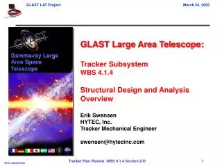
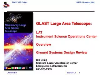
Large Area Telescope (LAT) Design Overview Instrument 16 towers modularity height/width = 0.4 large field-of-view Si-strip detectors: 228 mm pitch, total of 8.8 x 10⁵ ch, thin tungsten radiators hodoscopic CsI crystal array cosmic-ray rejection shower leakage correction XTkr + Cal = 10 X0 shower max contained < 100 GeV segmented plastic scintillator minimize self-veto > 0.9997 efficiency & redundant readout Tracker Calorimeter Anticoincidence Detector Shield 3000 kg, 650 W (allocation) 1.75 m 1.75 m 1.0 m 20 MeV – 300 GeV
Electronics boards attached to each side. Electronic readout to connectors at base of calorimeter. Outer wall is EMI shield and provides structural stiffness as well. Each Module 8 layers of 12 CsI(Tl) Crystals Crystal dimensions: 27 x 20 x 333 mm Hodoscopic stacking - alternating orthogonal layers Dual PIN photodiode on each end of crystals. Mechanical packaging – Carbon Composite cell structure Calorimeter Module Overview Modular Design 4 x 4 array of calorimeter modules
Calorimeter Technical Challenges • Imaging calorimetry to support background rejection and to improve energy measurement via shower profile correction or leakage estimation. • Longitudinal positioning in individual crystals using light asymmetry between ends of crystal • Large dynamic range (~5 x 10⁵) with low power electronics • Divide signal into 4 ranges using dual PIN photodiode of differing areas (two ranges per diode) • Custom CMOS ASIC front end electronics • Minimize passive material and gaps in active material caused by modular design, yet survive 6g launch loads. • Carbon composite structure with individual cells for each CsI crystal. • In-flight calibration • Use cosmic rays (p – Fe)
Manufacturing responsibilities • Sweden Deliverables • Receive xtals from vendor (Amcrys, Kharkov, Ukraine) 2040 xtals • Acceptance/verification tests • Ship to France • France • Assemble Crystal Detector Elements (CDEs) 2040 CDEs • Manufacture mechanical structure 18 structures • Test • Ship to NRL • Naval Research Lab • Assemble Calorimeter Module 18 modules • Manufacture front-end electronics • Integrate CDEs with structure and electronics • Test and calibration • Pre-Ship Review • Ship to SLAC for integration into LAT
PIN diodes • Derived from commercial photodiodes • Customized dimensions for GLAST • Uses standard manufacturing • Implement two diodes on single carrier • Single carrier for convenience • Need large diode for low energy threshold (~2 MeV) • Want small diode large enough for ground test with muons • Use flexible interconnect to AFEE BTEM ’99 Dual PIN Diodes Hamamatsu Photonics 96 mm2 and 24 mm2
Crystal-Detector Element • Combination of crystal, PIN diode, and wrapper is called Crystal Detector Element (CDE) • Careful choice of wrapper to optimize light yield • Use 3M specular reflector film VM2000 • Careful choice of bonding material for PIN diode-crystal bond • Nature of crystal (performs like oil-coated lead) makes adhesion difficult • CTE of CsI is large, while CTE of diode is small • Use DC93-500, a silicone elastomer with primer Beam test CDEs
Mechanical Structure French Contribution • Carbon fiber structure • Must hold ~80 kg of CsI at 6-g acceleration with ~10 kg of supporting material • Must manage thermal expansion of CsI • Mechanical details • 96 individual carbon cells • Al top, bottom, and side plate • Bottom plate is mechanical support for DAQ, control, and power supplies • Sides support AFEE boards
Electronics Design • Design • Need to cover a very large dynamic range • From threshold (~2 MeV) to 100 GeV in a crystal • Low noise (2000 electrons noise) • Low power (~20 mW per crystal end) • Limited space (8 mm thickness), match pitch of CsI crystals (28x40 mm) • Interface to Tower Electronics Module (TEM, remainder of DAQ chain) • Implementation • Use 1 custom analog and 1 custom digital ASIC to minimize power • Use 2 diodes with 2 channels each to reduce dynamic range requirement on electronics • Ranges to 200 MeV, 1.6 GeV, 12.5 GeV and 100 GeV • Use commercial 12-bit ADCs • Low dead time (20 s) • Zero suppression to reduce data volume
Calorimeter Status • CDE status: • Specification and procurement of CsI crystals is in place. • Specification and procurement of dual PIN photodiode prototypes is complete • 400 photodiodes have been received. • Bonding material, DC93-500 - a silicone elastomer, has been selected • Resolves CTE mismatch between CsI and PIN diode • Crystal wrapping material is from 3M – VM2000 specular reflector film • Mechanical structure status: • Prototype mechanical structure has been produced and is undergoing testing • Electronics status: • CAL Analog ASIC (GCFE) is in its 5th iteration and being tested. • CAL digital ASIC (GCRC) first submission occurred Dec 2001 • Commercial off-the-shelf (COTS) ADCs and other components have passed radiation hardness test. • CAL analog front end electronics boards (AFEE) have been prototyped
Production schedule • Engineering Module: • planned to be assembled and tested in 2002 • 130 CsI crystals for EM available now • Flight Modules: • CsI deliveries (1910 crystals): Apr 2002 – Apr 2003 • Cal module integration and tests : Nov 2002 – Dec 2003 • Instrument integration and test: Jan 2004 – March 2005 • Spacecraft integration and test: March 2005 – March 2006 • Launch: March 2006