Download
1 / 25
270 likes | 506 Views
Objectives. Explain the operation of an RC integratorAnalyze an RC integrator with a single input pulseAnalyze an RC integrator with repetitive input pulsesAnalyze an RC differentiator with a single input pulse. Objectives. Analyze an RC differentiator with repetitive input pulsesAnalyze the ope

E N D
1. Chapter 15 Time Response of Reactive Circuits
2. Objectives Explain the operation of an RC integrator
Analyze an RC integrator with a single input pulse
Analyze an RC integrator with repetitive input pulses
Analyze an RC differentiator with a single input pulse
3. Objectives Analyze an RC differentiator with repetitive input pulses
Analyze the operation of an RL integrator
Analyze the operation of an RL differentiator
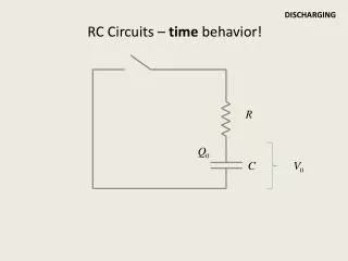
4. The RC Integrator When a pulse generator is connected to the input of an RC integrator, the capacitor will charge and discharge in response to the pulses
5. The RC Integrator The rate of charging and discharging depends on the RC time constant
? = RC
For an ideal pulse, both edges are considered to be instantaneous
The capacitor appears as a short to an instantaneous change in current and as an open to dc
The voltage across the capacitor cannot change instantaneously - it can change only exponentially
6. Capacitor Voltage In an RC integrator, the output is the capacitor voltage
The capacitor charges during the time that the pulse is high
If the pulse is at its high level long enough, the capacitor will fully charge to the voltage amplitude of the pulse
The capacitor discharges during the time that the pulse is low
7. Response of RC Integrators to Single-Pulse Inputs A capacitor will fully charge if the pulse width is equal to or greater than 5 time constants (5?)
At the end of the pulse, the capacitor fully discharges back through the source
8. When the Pulse Width is Equal to or Greater than 5 Time Constants As the pulse width is increased, the shape of the output pulse approaches that of the input
9. When the Pulse Width is Less Than 5 Time Constants The output voltage will not reach the full input voltage before the end of the pulse
The capacitor only partially charges
As the pulse width is reduced, the output voltage becomes smaller because the capacitor has less time to charge
However, it takes the capacitor approximately the same length of time (5?) to discharge back to zero after the pulse is removed
10. Repetitive-Pulse Response of RC Integrators If a periodic pulse waveform is applied to an RC integrator, the output waveshape depends on the relationship of the circuit time constant and the frequency (period) of the input pulses
If the pulse width and the time between pulses are each equal to or greater than five time constants (T>5?), the capacitor will fully charge and fully discharge during each period of the input waveform
11. When a Capacitor Does Not Fully Charge and Discharge When the pulse width and the time between pulses are shorter than five time constants, the capacitor will not completely charge or discharge
12. When a Capacitor Does Not Fully Charge and Discharge During the first pulse, the capacitor charges, the output voltage reaches 63.5%
Between the first and second pulses, the capacitor discharges, and the voltage decreases to (100% - 63.2%) = 36.8% of the voltage at the beginning of this interval
On the second pulse, the capacitor voltage increases another 63.2% of its full value, added to the value it started with
13. Steady-State Response The output voltage will build up to a steady-state average value in five time constants (5?)
If the time constant is extremely long compared to the pulse width, the output voltage approaches a constant dc voltage. This value is the average value of the input
For a square wave, the steady-state value is one-half of the input voltage
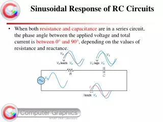
14. Single-Pulse Response of RC Differentiators A series RC circuit in which the output voltage is taken across the resistor is known as a differentiator. In terms of frequency response, it is a high-pass filter
The shape of the differentiator�s resistor voltage is determined by the charging and discharging action of the capacitor
The next slide shows the pulse response of a differentiator for: tW?5 ?, and tW?5?
16. Repetitive-Pulse Response of RC Differentiators As the time constant is reduced (tW<5?), both positive and negative portions of the output become narrower
The average value of the output is zero
For a very long time constant, the output approaches the shape of the input, but with an average value of zero
The average value of a waveform is its dc component
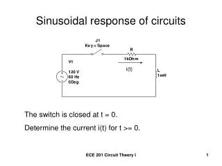
17. Analysis of a Repetitive Waveform Consider an RC differentiator with ? = tW, and an input waveform of 0 to +10V
18. Pulse Response of RL Integrators The output waveform is taken across the resistor, and under equivalent conditions, is the same shape as that for the RC integrator
When a pulse generator is connected to the input of the integrator and the voltage pulse goes from its low level to its high level, the inductor prevents a sudden change in current
The inductor acts as an open, and all of the input voltage is across it at the instant of the rising edge
19. Response of the Integrator to a Single Pulse
20. Pulse Response of an RL Differentiator A series RL circuit in which the output voltage is taken across the inductor is known as a differentiator
When the input pulse goes from its low level to its high level, L looks like an open, and all of the input voltage appears across it at the instant of the rising edge
Shown in the next slide are the responses of an RL differentiator for both time constant conditions
21. Pulse Response of an RL Differentiator
22. Summary In an RC integrating circuit, the output voltage is taken across the capacitor
In an RC differentiating circuit, the output voltage is taken across the resistor
In an RL integrating circuit, the output voltage is taken across the resistor
In an RL differentiating circuit, the output voltage is taken across the inductor
23. Summary In an integrator, when the pulse width (tW) of the input is much less than the transient time, the output voltage approaches a constant level equal to the average value of the input
In an integrator, when the pulse width of the input is much greater than the transient time, the output voltage approaches the shape of the input
24. Summary In a differentiator, when the pulse width of the input is much less than the transient time, the output voltage approaches the shape of the input but with an average value of zero
25. Summary In a differentiator , when the pulse width of the input is much greater than the transient time, the output voltage consists of narrow, positive-going and negative-going spikes occurring on the leading and trailing edges of the input pulses