Download
1 / 90
900 likes | 907 Views
Time Varying Circuits. 2008. A look into the future. We have one more week after today (+ one day) Time Varying Circuits Including AC Some additional topics leading to waves A bit of review if there is time. There will be one more Friday morning quiz.

E N D
Time Varying Circuits 2008 Induction
A look into the future • We have one more week after today (+ one day) • Time Varying Circuits Including AC • Some additional topics leading to waves • A bit of review if there is time. • There will be one more Friday morning quiz. • I hope to be able to return the exams on Monday at which time we will briefly review the solutions. Induction
The Final Exam • 8-10 Problems similar to (or exactly) Web-Assignments • Covers the entire semester’s work • May contain some short answer questions. Induction
Max Current Rate of increase = max emf VR=iR ~current Induction
We Solved the loop equation. Induction
We also showed that Induction
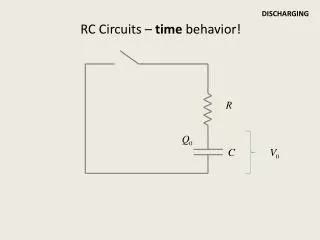
At t=0, the charged capacitor is now connected to the inductor. What would you expect to happen?? Induction
The math … For an RLC circuit with no driving potential (AC or DC source): Induction
The Graph of that LR (no emf) circuit .. I Induction
Mass on a Spring Result • Energy will swap back and forth. • Add friction • Oscillation will slow down • Not a perfect analogy Induction
LC Circuit High Q/C Low Low High Induction
The Math Solution (R=0): Induction
New Feature of Circuits with L and C • These circuits produce oscillations in the currents and voltages • Without a resistance, the oscillations would continue in an un-driven circuit. • With resistance, the current would eventually die out. Induction
Variable Emf Applied emf DC Sinusoidal Induction
Sinusoidal Stuff “Angle” Phase Angle Induction
Same Frequency with PHASE SHIFT f Induction
Different Frequencies Induction
Note – Power is delivered to our homes as an oscillating source (AC) This makes AC Important! Induction
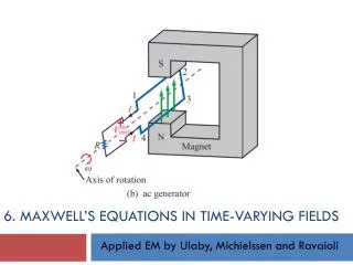
Producing AC Generator x x x x x x x x x x x x x x x x x x x x x x x x x x x x x x x x x x x x x x x x x x x x x x x x x x x x x x x x x x x x x x x x x x x x x x x x x x x x x x x x x x x x x x x x x x x x x x x x x x x x x x x x x x x x x x x x x x x x x x x x x x x x x x x x x x x x x x x x x x x x x x x x x x x x x x x x x x x x x x x x x x x x x x x x x x x x x x x x x x x x x x x x x x x x x x x x x x x x x x x x x x x x x x x x x x x x x x x x x x x x x x x x x x x x x x x x x x x x x x x x x x x x x x x x x x x x x x x x x x x x x x x x x x x x x x x x x x x x Induction
The Real World Induction
A Induction
The Flux: Induction
problems … Induction
14. Calculate the resistance in an RL circuit in which L = 2.50 H and the current increases to 90.0% of its final value in 3.00 s. Induction
18. In the circuit shown in Figure P32.17, let L = 7.00 H, R = 9.00 Ω, and ε = 120 V. What is the self-induced emf 0.200 s after the switch is closed? Induction
32. At t = 0, an emf of 500 V is applied to a coil that has an inductance of 0.800 H and a resistance of 30.0 Ω. (a) Find the energy stored in the magnetic field when the current reaches half its maximum value. (b) After the emf is connected, how long does it take the current to reach this value? Induction
16. Show that I = I0e – t/τ is a solution of the differential equation where τ = L/R and I0 is the current at t = 0. Induction
17. Consider the circuit in Figure P32.17, taking ε = 6.00 V, L = 8.00 mH, and R = 4.00 Ω. (a) What is the inductive time constant of the circuit? (b) Calculate the current in the circuit 250 μs after the switch is closed. (c) What is the value of the final steady-state current? (d) How long does it take the current to reach 80.0% of its maximum value? Induction
27. A 140-mH inductor and a 4.90-Ω resistor are connected with a switch to a 6.00-V battery as shown in Figure P32.27. (a) If the switch is thrown to the left (connecting the battery), how much time elapses before the current reaches 220 mA? (b) What is the current in the inductor 10.0 s after the switch is closed? (c) Now the switch is quickly thrown from a to b. How much time elapses before the current falls to 160 mA? Induction
52. The switch in Figure P32.52 is connected to point a for a long time. After the switch is thrown to point b, what are (a) the frequency of oscillation of the LC circuit, (b) the maximum charge that appears on the capacitor, (c) the maximum current in the inductor, and (d) the total energy the circuit possesses at t = 3.00 s? Induction
Source Voltage: Induction
Average value of anything: h T Area under the curve = area under in the average box Induction
Average Value For AC: Induction
So … • Average value of current will be zero. • Power is proportional to i2R and is ONLY dissipated in the resistor, • The average value of i2 is NOT zero because it is always POSITIVE Induction
Average Value Induction
RMS Induction
Usually Written as: Induction
R E ~ Example: What Is the RMS AVERAGE of the power delivered to the resistor in the circuit: Induction
Power Induction
More Power - Details Induction
Resistive Circuit • We apply an AC voltage to the circuit. • Ohm’s Law Applies Induction
Consider this circuit CURRENT ANDVOLTAGE IN PHASE Induction
A protion of next group of slides is stolen from Dr. Braunstein. Induction
V(t) Vp wt p 2p fv -Vp An “AC” circuit is one in which the driving voltage and hence the current are sinusoidal in time. Alternating Current Circuits V = VP sin (wt - fv ) I = IP sin (wt - fI ) wis theangular frequency (angular speed) [radians per second]. Sometimes instead ofwwe use thefrequency f [cycles per second] Frequency f [cycles per second, or Hertz (Hz)]w= 2p f Induction
V(t) Vp wt p 2p fv -Vp Phase Term V = VP sin (wt - fv ) Induction
V(t) Vp wt p 2p fv -Vp V = VP sin (wt - fv ) I = IP sin (wt - fI ) Alternating Current Circuits I(t) Ip Irms Vrms t fI/w -Ip Vp and Ip are the peak current and voltage. We also use the “root-mean-square” values: Vrms = Vp / and Irms=Ip / fv andfI are called phase differences (these determine when V and I are zero). Usually we’re free to set fv=0 (but not fI). Induction
Example: household voltage In the U.S., standard wiring supplies 120 V at 60 Hz. Write this in sinusoidal form, assuming V(t)=0 at t=0. Induction