Download
1 / 12
120 likes | 128 Views
RiSE State-Based Voltage Control. Salomon Trujillo, July 13, 2007. Video. Joint Speed Comparison. Measured Voltage Comparison. DC Motor Model. τ. V = K τ τ + K ω ω I = K I τ. High current draw. Stall Torque V motor. Constant slope. No current draw. ω. Area = Power. No-Load

E N D
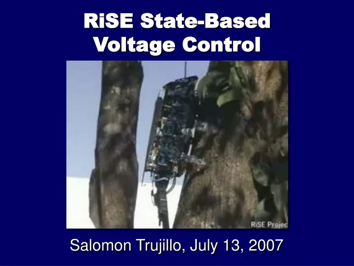
RiSE State-BasedVoltage Control Salomon Trujillo, July 13, 2007
DC Motor Model τ V = Kττ + Kωω I = KIτ High current draw Stall Torque Vmotor Constant slope No current draw ω Area = Power No-Load Speed Vmotor
ω kp u - f + kd uω - Kf f V + Kω ω PD & Force Control Diagrams
Voltage Control of Motors Wing Voltage Motor B Voltage Motor A Voltage Crank Voltage
Gait State Machine Wing Voltage Pull Down Front Release Front Flight Front Strike Crank Voltage Back Release Back Flight Back Strike Front Legs Pull Down Back Legs
Yaw Bang-Bang Control u Yaw detected using IMU
Flight-Brake Control v Constant velocity approach Braking Curve x Target State
Pitch Correction Pitch detected using IMU and wing angles Normal Attachment Pitch Correction Attachment
Future Work • Produce a hybrid control that combines trajectory and state-based controllers. • Build a framework that uses robot dynamics to calculate desired voltages. • Experiment with voltage commands at transitions (input shaping?) • Work on release and strike states to provide smoother attachment & detachment and prevent non-gravity deceleration.