Download
1 / 13
130 likes | 137 Views
Beam Windows for high transverse density beams. By the CERN «Groupe Méthodes» Presented by L.Bruno AB/ATB Targets & Dumps Section. Beam Windows For high transverse density beams. OUTLINE 1. Statement of the problem 2. Standard window systems 3. New developments

E N D
Beam Windows for high transverse density beams By the CERN «Groupe Méthodes» Presented by L.Bruno AB/ATBTargets & Dumps Section
Beam Windows For high transverse density beams OUTLINE 1. Statement of the problem 2. Standard window systems 3. New developments 4. Window materials 5. Summary
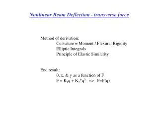
The structural problemPrimary static membrane stresses Titanium a = 30 mm(Beam Line)sc = 264 MPayc = 1.4 mma = 50 mm(Target Unit)sc = 339 MPayc = 2.7 mm q=1 bar = 0° sc Thickness t=0.1mm The structural problem implies large displace-ments (yc>t/2), which call for iterative solutions. Solid circular disc fixed and heldunder uniformly distributed pressure
Comparison: Beryllium windowsPrimary static membrane stresses Beryllium Ø 2.5” (a=~32mm)(Beam Line)sc = 166 MPayc = 0.37 mmØ 4” (a=~51mm)(Target Unit)sc = 222 MPayc = 0.84 mm q=1 bar = 0° sc Thickness Ø 2.5” : t=0.020” (0.508mm) Ø 4” : t=0.025” (0.635mm) The structural problem implies large displace-ments (yc>t/2), which call for iterative solutions. Solid circular disc fixed and heldunder uniformly distributed pressure
544°C 758°C Temperature distributionCNGS beam parameters Beam sigma = 0.53 mmNominal int. = 2.4 1013 pUltimate int. = 3.5 1013 p Ultimateintensity Temperatures too high Nominalintensity M.Sans r [mm] The temperature distribution induced by the CNGS beam was evaluated by FLUKA. Temperatures higher than 50°C are affected by statistical errors <1%. The simulation covered 3 107 events with a 0.25mm x 0.1mm axi-symmetric binning.
150°C 205°C Comparison: Beryllium windows CNGS beam parameters Ultimateintensity Beam sigma = 0.530 mmNominal int. = 2.4 1013 pUltimate int. = 3.5 1013 p SF=0.64@ 200°CSF=0.73@ 300°C a=~32mm Nominalintensity SF=0.85@ 200°CSF=0.97@ 300°C a=~51mm M.Sans r [mm] The temperature distribution induced by the CNGS beam was evaluated by FLUKA. Temperatures higher than 50°C are affected by statistical errors <1%. The simulation covered 3 107 events with a 0.4mm x 0.1mm axi-symmetric binning.
266°C 372°C Temperature distributionTest case: Beam sigma = 0.795 mm Ultimateintensity Beam sigma = 0.795 mmNominal int. = 2.4 1013 pUltimate int. = 3.5 1013 p SF=0.61@ 300°CSF=0.69@ 400°C a=30mm Nominalintensity SF=0.78@ 300°CSF=0.88@ 400°C a=50mm M.Sans r [mm] The temperature distribution induced for a test case beam was evaluated by FLUKA. Temperatures higher than 50°C are affected by statistical errors <1%. The simulation covered 3 107 events with a 0.4mm x 0.1mm axi-symmetric binning.
Beam sigma = 0.795 mmNominal int. = 2.4 1013 p 266°C 199°C @ t=50ms T [°C] Temperature evolutionat the beam spot – Test case t[ms] Titanium has a relativelylow thermal diffusivity of 2.7 mm2/s (as a comparison, graphite has 75 mm2/s). This value implies a build-up of temperature at the second extraction.
BrazedWindows (SPS beam obstacles and monitors) Brazed joint “knife” “knife” Weld Air Vacuum Flange Flange Foil
Vacuum Air Helicoflex joint Foil Captive Windows (nTOF Fast Induction Chamber) Vacuum system
Reinforced Captive Windows Vacuum Reinf. Air Helicoflex joint Foil
Window Materials Captive reinforced windows Captive windows (L.Bruno, S.Sgobba)
Status and Future Activities High specific heat,thermal diffusivity and physical/chemical stability (e.g. crystal growth, oxidation resistance) are key factors; De-coupling the pressure-bearing from the leak-tighness function eases design and lowers costs; Standard iterative analytical design formulas are very conservative for ductile materials. Thermal stresses, stress waves, fatigue, axial shocks are to be studied. Tests are planned at CERN under CNGS nominal beam load.