Download
1 / 38
460 likes | 824 Views
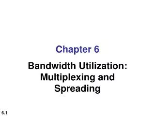
Chapter 6 Bandwidth Utilization: Multiplexing and Spreading. 6-1 MULTIPLEXING. Whenever the bandwidth of a medium linking two devices is greater than the bandwidth needs of the devices, the link can be shared.

E N D
Chapter 6 Bandwidth Utilization: Multiplexing and Spreading
6-1 MULTIPLEXING • Whenever the bandwidth of a medium linking two devices is greater than the bandwidth needs of the devices, the link can be shared. • Multiplexing is the set of techniques that allows the simultaneous transmission of multiple signals across a single data link. • As data and telecommunications use increases, so does traffic.
Figure 6.4 FDM process FDM is an analog multiplexing technique that combines analog signals.
Example 6.1 Assume that a voice channel occupies a bandwidth of 4 kHz. We need to combine three voice channels into a link with a bandwidth of 12 kHz, from 20 to 32 kHz. Show the configuration, using the frequency domain. Assume there are no guard bands. Solution We shift (modulate) each of the three voice channels to a different bandwidth, as shown in Figure 6.6. We use the 20- to 24-kHz bandwidth for the first channel, the 24- to 28-kHz bandwidth for the second channel, and the 28- to 32-kHz bandwidth for the third one. Then we combine them as shown in Figure 6.6.
Example 6.2 Five channels, each with a 100-kHz bandwidth, are to be multiplexed together. What is the minimum bandwidth of the link if there is a need for a guard band of 10 kHz between the channels to prevent interference? Solution For five channels, we need at least four guard bands. This means that the required bandwidth is at least 5 × 100 + 4 × 10 = 540 kHz,
Figure 6.9 Analog hierarchy 12 5 10 Have guard bands 6 Have guard bands
Figure 6.10 Wavelength-division multiplexing WDM is an analog multiplexing technique to combine optical signals.
Figure 6.11 Prisms in wavelength-division multiplexing and demultiplexing A prism bends a beam of light based on the angle of incidence and the frequency
Figure 6.12 TDM • TDM is a digital multiplexing technique for combining several low-rate channels into one high-rate one. • Two types: synchronous and statistical
Figure 6.13 Synchronous time-division multiplexing • In synchronous TDM, each input connection has an allotment in the output even if it is not sending data. • In synchronous TDM, the data rate of the link is n times faster, and the unit duration is n times shorter.
Example 6.5 In Figure 6.13, the data rate for each input connection is 1 kbps. If 1 bit at a time is multiplexed (a unit is 1 bit), what is the duration of (a) each input slot, (b) each output slot, and (c) each frame? Solution We can answer the questions as follows: a. The data rate of each input connection is 1 kbps. This means that the bit duration is 1/1000 s or 1 ms. The duration of the input time slot is 1 ms (same as bit duration).
Example 6.5 (continued) b. The duration of each output time slot is one-third of the input time slot. This means that the duration of the output time slot is 1/3 ms. c. Each frame carries three output time slots. So the duration of a frame is 3 × 1/3 ms, or 1 ms. The duration of a frame is the same as the duration of an input unit.
Example 6.9 A multiplexer combines four 100-kbps channels using a time slot of 2 bits. Show the output with four arbitrary inputs. What is the frame rate? What is the frame duration? What is the bit rate? What is the bit duration?
Figure 6.17 Example 6.9 Solution Figure 6.17 shows the output for four arbitrary inputs. The link carries 50,000 frames per second. The frame duration is therefore 1/50,000 s or 20 μs. The frame rate is 50,000 frames per second, and each frame carries 8 bits; the bit rate is 50,000 × 8 = 400,000 bits or 400 kbps. The bit duration is 1/400,000 s, or 2.5 μs.
Example 6.10 We have four sources, each creating 250 characters per second. If the interleaved unit is a character and 1 synchronizing bit is added to each frame, find (a) the data rate of each source, (b) the duration of each character in each source, (c) the frame rate, (d) the duration of each frame, (e) the number of bits in each frame, and (f) the data rate of the link. Solution We can answer the questions as follows: a. The data rate of each source is 250 × 8 = 2000 bps = 2 kbps.
Example 6.10 (continued) b. Each source sends 250 characters per second; therefore, the duration of a character is 1/250 s, or 4 ms. c. Each frame has one character from each source, which means the link needs to send 250 frames per second to keep the transmission rate of each source. d. The duration of each frame is 1/250 s, or 4 ms. Note that the duration of each frame is the same as the duration of each character coming from each source. e. Each frame carries 4 characters and 1 extra synchronizing bit. This means that each frame is 4 × 8 + 1 = 33 bits.
Figure 6.18 Empty slots Synchronous TDM is not always efficient
Example 6.11 Two channels, one with a bit rate of 100 kbps and another with a bit rate of 200 kbps, are to be multiplexed. How this can be achieved? What is the frame rate? What is the frame duration? What is the bit rate of the link? Solution We can allocate one slot to the first channel and two slots to the second channel. Each frame carries 3 bits. The frame rate is 100,000 frames per second because it carries 1 bit from the first channel. The bit rate is 100,000 frames/s × 3 bits per frame, or 300 kbps.
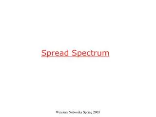
6-1 SPREAD SPECTRUM In spread spectrum (SS), we combine signals from different sources to fit into a larger bandwidth, but our goals are to prevent eavesdropping and jamming. To achieve these goals, spread spectrum techniques add redundancy.
Figure 6.27 Spread spectrum Bss >> B 1 Wrap message in a protective envelope for a more secure transmission. 2 the expanding must be done independently 3 two types: frequency hopping spread spectrum (FHSS) and direct sequence spread spectrum (DSSS)
Figure 6.32 DSSS Direct sequence spread spectrum Replace each data bit with n bits using a spreading code