Download
1 / 23
280 likes | 981 Views
Team Members: Jarret Vian Bryan Rowley John Murray. ME 191 Final Presentation Spring 2009. FSAE Suspension. Outline. Introduction Re-Design Manufacturing Testing Conclusion. Introduction. Design Requirements. Minimum 60” wheel base Unequal front & rear track widths

E N D
Team Members: Jarret Vian Bryan Rowley John Murray ME 191 Final Presentation Spring 2009 FSAESuspension
Outline • Introduction • Re-Design • Manufacturing • Testing • Conclusion
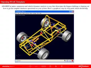
Design Requirements • Minimum 60” wheel base • Unequal front & rear track widths • Minimum 1” ground clearance • Minimum 2” total suspension travel • Template must pass through frame • Spherical bearings must be in double shear • Design must handle applied loading Design Goal • Rate of camber angle change with respect to both body roll and wheel displacement
Re-Design • Original • Final Design
Manufacturing • Manufactured at CSUS, by FSAE team
Manufacturing • A - Arms
Bearing Holder • Hub & Spindle • Upright
Geometry Testing • Wheelbase • Track Width • Camber • Caster
Goals • Rate of camber angle change per degree body roll
Upright Testing • Strain Gages
Strain Gage Installation • Degrease • Abrade • Burnish • Condition • Neutralize • M-Bond 200 • Solder • Connect to instrumentation
Loading Scenario: 759lbs • Apply the load, and maintain a constant force on the tire • 139lbs, 300lbs, 400lbs • Read the strain from each channel on the instrumentation
Stress Extrapolation • Elastic
FEA Stress Value • Rosette location • Probe
Theoretical Experimental • Sy = 50,800psi • Assumption: rigid • Assumption: smooth
Future Testing Plans • Strain gauge and accelerometer data logged during driving • Mychron 3 data logger with internal Accelerometer • Strain gauges
Lessons Learned • Engineering is challenging and rewarding • Never underestimate the scope of a project • Always test to verify assumptions