Download
1 / 23
240 likes | 278 Views
Understand the importance of system modeling in requirements engineering, learn about behavioral, data, and object modeling, explore the Unified Modeling Language (UML) and how CASE workbenches support system modeling. Different model types and perspectives are discussed. The UML and its versions, along with context, process, and behavioral models are examined, providing insights into modeling systems effectively for communication with stakeholders.

E N D
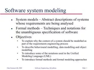
Objectives • To explain why the context of a system should be modelled as part of the RE process • To describe behavioural modelling, data modelling and object modelling • To introduce some of the notations used in the Unified Modeling Language (UML) • To show how CASE workbenches support system modelling
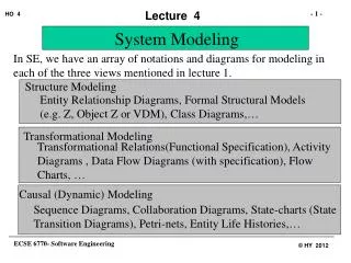
System modelling • System modelling helps the analyst to understand the functionality of the system and models are used to communicate with customers. • Different models present the system from different perspectives • External perspective showing the system’s context or environment; • Behavioural perspective showing the behaviour of the system; • Structural perspective showing the system or data architecture.
Model types • Data processing model showing how the data is processed at different stages. • Composition model showing how entities are composed of other entities. • Architectural model showing principal sub-systems. • Classification model showing how entities have common characteristics. • Stimulus/response model showing the system’s reaction to events.
The Unified Modeling Language (UML) • The UML has become a standard diagrammatic notation for developing models of object-oriented systems. • The UML is a unification of a range of different approaches to OO modelling that were developed in the 1990s. • Its latest version (UML 2) also includes more general modelling constructs. • UML 1 was the most widely used when this chapter was written. I have therefore used this notation here. Consequently, some diagrams such as data-flow diagrams are not expressed in the UML.
UML 2 model types • UML 2 has 13 different types of diagram that are used to model different aspects of a system • Behavioural diagrams are used to model behavioural features of a system. For example, use-case diagrams, activity diagrams, state machine diagrams • Interaction diagrams are used to model interactions between entities in the system. For example, sequence diagrams and communication diagrams. • Structure diagrams are used to model the organization of the system. For example, class diagrams, package diagrams, and deployment diagrams.
Context models • Context models are used to illustrate the operational context of a system - they show what lies outside the system boundaries. • Social and organisational concerns may affect the decision on where to position system boundaries. • Architectural models show the system and its relationship with other systems.
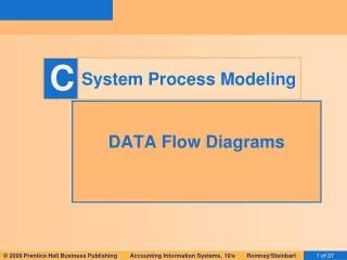
Process models • Process models show the overall process and the processes that are supported by the system. • Data flow models may be used to show the processes and the flow of information from one process to another. • These types of diagram are sometimes known as workflow diagrams.
Behavioural models • Behavioural models are used to describe the overall behaviour of a system. • Two types of behavioural model are: • Data processing models that show how data is processed as it moves through the system; • State machine models that show the systems response to events. • These models show different perspectives so both of them are required to describe the system’s behaviour.
Data-processing models • Data flow diagrams (DFDs) may be used to model the system’s data processing. • These show the processing steps as data flows through a system. • DFDs are an intrinsic part of many analysis methods. • Simple and intuitive notation that customers can understand. • Show end-to-end processing of data.
Data flow diagrams • DFDs model the system from a functional perspective. • Tracking and documenting how the data associated with a process is helpful to develop an overall understanding of the system. • Data flow diagrams may also be used in showing the data exchange between a system and other systems in its environment.
UML diagrams • To model workflow or data-flow, you can use UML 2 activity diagrams. • These provide a richer notation that that used here so translation is simple • UML state machine diagrams may be used to model how events are processed by a system
State machine models • These model the behaviour of the system in response to external and internal events. • They show the system’s responses to stimuli so are often used for modelling real-time systems. • State machine models show system states as nodes and events as arcs between these nodes. When an event occurs, the system moves from one state to another. • Statecharts are an integral part of the UML and are used to represent state machine models.
Statecharts • Allow the decomposition of a model into sub-models (see following slide). • A brief description of the actions is included following the ‘do’ in each state. • Can be complemented by tables describing the states and the stimuli.
Key points • A model is an abstract system view. Complementary types of model provide different system information. • Context models show the position of a system in its environment with other systems and processes. • Data flow models may be used to model the data processing in a system. • State machine models model the system’s behaviour in response to internal or external events