Download
1 / 19
190 likes | 304 Views
A/C GENERATORS. PRINCIPLES OF OPERATION. OPERATION. The generator converts mechanical energy into electrical energy. Mechanical energy is given by means of a drive belt, from the crankshaft. MAJOR COMPONENTS. Housing ( drive and rear) Rotor Stator Rectifier Brush Assembly

E N D
A/C GENERATORS PRINCIPLES OF OPERATION
OPERATION • The generator converts mechanical energy into electrical energy. • Mechanical energy is given by means of a drive belt, from the crankshaft.
MAJOR COMPONENTS • Housing ( drive and rear) • Rotor • Stator • Rectifier • Brush Assembly • Voltage Regulator (Integral) • Drive Pulley
HOUSINGS • Drive Housing: Supports the front of the rotor shaft, as a large bearing pressed or flanged bolted. Has mounting holes for installation on to engine via a bracket. • End Housing: Anchoring point for Brush holder, Regulator, Rectifier and Stator assembly. Also supports the rear of the rotor shaft via small bearing.
ROTOR • Purpose: The rotor is used to create a magnetic field, and rotate that magnetic field inside the stator at varying speeds. • Parts • Projections (2) North and South • Rotor shaft • Field Windings • Slip Rings
BRUSHES AND SLIP RINGS • Purpose: To direct current to the rotating field windings • Connections • F (field terminal) External • Voltage regulator (insulated) • Exciter Diodes
STATOR • Purpose: To collect the magnetic field created by the rotor • Parts • 3 or 4 phase windings • Laminated steel frame • Winding types • Wye • Delta
STATOR • The Stator produces a Analog Signal, that produces Alternating Current • Output is determined by • Magnetic field strength • Rotor speed • Winding type (delta or wye) • Winding length • Number of phases (windings)
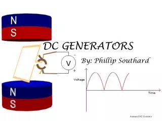
Rectification • Purpose: Change the current from AC to DC • Parts • Diodes: Three positive and three negative. • Exciter Diodes: Controls field current at Startup giving us full field current after start-up. • Heat Sink: Aluminum webbing linking diodes to end frame.
Voltage Regulator • Purpose: To control the current flow through the field windings. • Process: Switches current flow on and off in the field windings, by watching line voltage