Download
1 / 58
610 likes | 994 Views
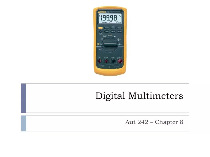
Digital Multimeters. Aut 242 – Chapter 8. OBJECTIVES. After studying Chapter 8, the reader should be able to: Prepare for ASE Electrical/Electronic Systems (A6) certification test content area “A” (General Electrical/Electronic System Diagnosis).

E N D
Digital Multimeters Aut 242 – Chapter 8
OBJECTIVES After studying Chapter 8, the reader should be able to: • Prepare for ASE Electrical/Electronic Systems (A6) certification test content area “A” (General Electrical/Electronic System Diagnosis). • Explain how to set a digital meter to read voltage, resistance, and current. • Explain meter terms and ratings. • Interpret meter readings and compare to factory specifications. • Discuss how to properly and safely use meters.
FUSED JUMPER WIREDEFINITION • A fused jumper wire is used to check a circuit by bypassing the switch or to provide a power or ground to a component. • A fused jumper wire, also called a lead, can be purchased or made by the service technician. • It should include the following features. • Fuse/Circuit Breaker • Alligator clip ends • Good-quality insulated wire
FIGURE 8–1 A technician-made fused jumper lead, which is equipped with a red 10 ampere fuse. This fused jumper wire uses terminals for testing circuits at a connector instead of alligator clips. FUSED JUMPER WIREDEFINITION
FUSED JUMPER WIREUSES OF A FUSED JUMPER WIRE • A fused jumper wire can be used to help diagnose a component or circuit by performing the following procedures. • Supply power or ground
TEST LIGHTS • A test light is simply a light bulb with a probe and a ground wire attached. • 12-volt test light is attached to a good ground while probing for power.
A test light can be used to locate an open in a circuit. Note that the test light is grounded at a different location than the circuit itself. TEST LIGHTS
TEST LIGHTS Continuity Test Lights • A continuity light illuminates whenever it is connected to both ends of a wire that has continuity or is not broken. • Self-powered test lights contain a battery, clamp, and probe. • This type of test light should not be used on any computer-controlled circuits because the applied voltage can damage delicate electronic components or circuits.
TEST LIGHTS LED Test Lights • An LED test light uses an LED instead of a standard automotive bulb for a visual indication of voltage.
LED Test LightHigh-impedance test light. • An LED test light can be easily made using low-cost components and an old ink pen. • With the 470 ohm resistor in series with the LED, this tester only draws 0.025 ampere (25 milliamperes) from the circuit being tested. • This low current draw helps assure the technician that the circuit or component being tested will not be damaged by excessive current flow.
TEST LIGHTS Logic Probe • A logic probe is an electronic device that lights up a red (usually) LED if the probe is touched to battery voltage. • A logic probe connected to the vehicle battery and relay used to check for power, ground, or a pulse.
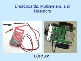
DIGITAL MULTIMETERS • Digital multimeter (DMM) and digital volt-ohmmilliammeter (DVOM) are terms commonly used for electronic high-impedance test meters.
Typical digital multimeter. The black meter lead always is placed in the COM terminal. Except when measuring the current in amperes, the red meter test lead remains in the V terminal. DIGITAL MULTIMETERS
Common abbreviations used on the display face of many digital multimeters. (Courtesy of Fluke Corporation) DIGITAL MULTIMETERS
A summary chart indicating what measurement type may be used to test which vehicle system. DIGITAL MULTIMETERS
DIGITAL MULTIMETERSMeasuring Voltage • A voltmeter measures the pressure or potential of electricity in units of volts. • A voltmeter is connected to a circuit in parallel.
A typical autoranging digital multimeter automatically selects the proper scale to read the voltage being tested. The scale selected is usually displayed on the meter face. (a) Note that the display indicates “4,” meaning that this range can read up to 4 volts. (b) The range is now set to the 40 volt scale, meaning that the meter can read up to 40 volts on the scale. Any reading above this level will cause the meter to reset to a higher scale. If not set on autoranging, the meter display would indicate OL if a reading exceeds the limit of the scale selected. (Courtesy of Fluke Corporation) DIGITAL MULTIMETERSMeasuring Voltage
Typical digital multimeter (DMM) set to read DC volts. DIGITAL MULTIMETERSMeasuring Voltage
DIGITAL MULTIMETERSMeasuring Resistance • An ohmmeter measures the resistance in ohms of a component or circuit section when no current is flowing through the circuit.
DIGITAL MULTIMETERSMeasuring Resistance Using a digital multimeter set to read ohms () to test this light bulb. The meter reads the resistance of the filament. Typical digital multimeter showing OL (over limit) on the readout with the ohms () unit selected. This usually means that the unit being measured is open (infinity resistance) and has no continuity.
Many digital multimeters can have the display indicate zero to compensate for test lead resistance. Connect leads in the Vand COM meter terminals Select the scale Touch the two meter leads together Push the “zero” or “relative” button on the meter The meter display will now indicate zero ohms of resistance. DIGITAL MULTIMETERSMeasuring Resistance
How Much Voltage Does an Ohmmeter Apply? • Most digital meters that are set to measure ohms (resistance) apply 0.3 to 1 volt to the component being measured. The voltage comes from the meter itself to measure the resistance. Two things are important to remember about an ohmmeter. • The component or circuit must be disconnected from any electrical circuit while the resistance is being measured. • Because the meter itself applies a voltage (even though it is relatively low), a meter set to measure ohms can damage electronic circuits. Computer or electronic chips can be easily damaged if subjected to only a few milliamperes of current, similar to the amount an ohmmeter applies when a resistance measurement is being performed.
Fuse Your Meter Leads! • Most digital meters include an ammeter capability. When reading amperes, the leads of the meter must be changed from volts or ohms (V or Ω) to amperes (A), milliamperes (mA), or microamperes (μA).
Fuse Your Meter Leads! • A common problem may then occur the next time voltage is measured. Although the technician may switch the selector to read volts, often the leads are not switched back to the volt or ohm position. Because the ammeter lead position results in zero ohms of resistance to current flow through the meter, the meter or the fuse inside the meter will be destroyed if the meter is connected to a battery. Many meter fuses are expensive and difficult to find.
Fuse Your Meter Leads! • To avoid this problem, simply solder an inline 10 ampere blade-fuse holder into one meter lead. • Do not think that this technique is for beginners only. • Experienced technicians often get in a hurry and forget to switch the lead. • A blade fuse is faster, easier, and less expensive to replace than a meter fuse or the meter itself. • Also, if the soldering is done properly, the addition of an inline fuse holder and fuse does not increase the resistance of the meter leads. • All meter leads have some resistance. If the meter is measuring very low resistance, touch the two leads together and read the resistance (usually no more than 0.2 ohm). • Simply subtract the resistance of the leads from the resistance of the component being measured.
DIGITAL MULTIMETERSMeasuring Amperes • An ammeter measures the flow of current through a complete circuit in units of amperes.
In this digital multimeter set to read DC amperes, note that the red lead is placed in the far left-hand socket of the meter. The meter is displaying the current flow (5.60 A) through the horn. DIGITAL MULTIMETERSMeasuring Amperes
AC/DC CLAMP-ON DIGITAL MULTIMETER • An AC/DC clamp-on digital multimeter (DMM) is a useful meter for automotive diagnostic work and uses a Hall effect sensor to measure current.
AC/DC CLAMP-ON DIGITAL MULTIMETER A typical mini clamp-on-type digital multimeter. This meter is capable of measuring alternating current (AC) and direct current (DC) without requiring that the circuit be disconnected to install the meter in series. The jaws are simply placed over the wire and current flow through the circuit is displayed. An AC and DC current clamp such as the one shown can be used with a regular digital multimeter. The amp probe contains a separate battery and electronic circuit that converts the amperage reading into a millivolt (mV) signal.
INDUCTIVE AMMETERSOPERATION • An inductive ammeter clamp is used with all starting and charging testers to measure the current flow through the battery cables.
ELECTRICAL UNIT PREFIXES • Electrical units are measured in numbers such as 12 volts, 150 amperes, and 470 ohms. • Kilo (k) means 1,000. • If the value is over 1 million (1,000,000), then the prefix mega (M) is often used. • Small units of measure expressed in 1/1,000 are prefixed by milli (m). • The micro unit is represented by the Greek letter mu (μ).
HOW TO READ DIGITAL METERS • Getting to know and use a digital meter takes time and practice. • Select the proper unit of electricity for what is being measured. • Place the meter leads into the proper input terminals. • Measure the component being tested. • Interpret the reading. Do you see a problem with this picture?
HOW TO READ DIGITAL METERS Always look at the meter display when a measurement is being made, especially if using an autoranging meter.
HOW TO READ DIGITAL METERSRMS versus Average • Alternating current voltage waveforms can be true sinusoidal or nonsinusoidal. • A true sine wave pattern measurement will be the same for both root-mean-square (RMS) and average reading meters.
HOW TO READ DIGITAL METERSRMS versus Average • When reading AC voltage signals, a true RMS meter (such as a Fluke 87) provides a different reading than an average responding meter (such as Fluke 88).The only place this difference is important is when a reading is to be compared with a specification.
HOW TO READ DIGITAL METERSResolution, Digits, and Counts • Meter resolution refers to how small or fine a measurement the meter can make. • The terms digits and counts are used to describe a meter’s resolution. • DMMs are grouped by the number of counts or digits they display.
This meter display shows 052.2 AC volts. Notice that the zero beside the 5 indicates that the meter can read over 100 volts AC with a resolution of 0.1 volt. HOW TO READ DIGITAL METERSResolution, Digits, and Counts
HOW TO READ DIGITAL METERSAccuracy • Meter accuracy is the largest allowable error that will occur under specific operating conditions. • Accuracy for a DMM is usually expressed as a percent of reading. • An accuracy of 1% of reading means that for a displayed reading of 100.0 V, the actual value of the voltage could be anywhere between 99.0 V to 101.0 V.
HOW TO READ DIGITAL METERSAccuracy • Unacceptable 1.00% • Okay 0.50% (1/2%) • Good 0.25% (1/4%) • Excellent 0.10% (1/10%) $4.00
Meter Usage on Hybrid Electric Vehicles • Many hybrid electric vehicles use system voltage as high as 650 volts DC. Be sure to follow all vehicle manufacturer’s testing procedures; and if a voltage measurement is needed, be sure to use a meter and test leads that are designed to insulate against high voltages. The International Electrotechnical Commission (IEC) has several categories of voltage standards for meter and meter leads. These categories are ratings for overvoltage protection and are rated CAT I, CAT II, CAT III, and CAT IV. The higher the category, the greater the protection against voltage spikes caused by high-energy circuits. Under each category there are various energy and voltage ratings.
Meter Usage on Hybrid Electric Vehicles • CAT I Typically a CAT I meter is used for lowenergy voltage measurements such as at wall outlets in the home. Meters with a CAT I rating are usually rated at 300 to 800 volts. • CAT II This higher rated meter would be typically used for checking higher energy level voltages at the fuse panel in the home. Meters with a CAT II rating are usually rated at 300 to 600 volts.
Meter Usage on Hybrid Electric Vehicles • CAT III This minimum rated meter should be used for hybrid vehicles. The CAT III category is designed for high-energy levels and voltage measurements at the service pole at the transformer. Meters with this rating are usually rated at 600 to 1,000 volts. • CAT IV CAT IV meters are for clamp-on meters only. If a clamp-on meter also has meter leads for voltage measurements, that part of the meter will be rated as CAT III.
METER USAGE ON HYBRID ELECTRIC VEHICLES Be sure to only use a meter that is CAT III rated when taking electrical voltage measurements on a hybrid vehicle. Always use meter leads that are CAT III rated on a meter that is also CAT III rated to maintain the protection needed when working on hybrid vehicles. FIGURE
SUMMARY • Digital multimeter (DMM) and digital volt-ohm-milliammeter (DVOM) are terms commonly used for electronic high-impedance test meters. • Use of a high-impedance digital meter is required on any computer-related circuit or component. • Ammeters measure current and must be connected in series in the circuit. • Voltmeters measure voltage and are connected in parallel. • Ohmmeters measure resistance of a component and must be connected in parallel, with the circuit or component disconnected from power. • Logic probes can indicate the presence of ground, as well as power.
REVIEW QUESTIONS • Explain why most digital meters are called high-impedance meters. • Describe how an ammeter should be connected to an electrical circuit. • Explain why an ohmmeter must be connected to a disconnected circuit or component.
CHAPTER QUIZ • Inductive ammeters work because of what principle? • Magic • Electrostatic electricity • A magnetic field surrounds any wire carrying a current • Voltage drop as it flows through a conductor
CHAPTER QUIZ 2. A meter used to measure amperes is called a(n) _____. • Amp meter • Ampmeter • Ammeter • Coulomb meter
CHAPTER QUIZ 3. A voltmeter should be connected to the circuit being tested _____. • In series • In parallel • Only when no power is flowing • Both a and c