Download
1 / 86
1.26k likes | 1.81k Views
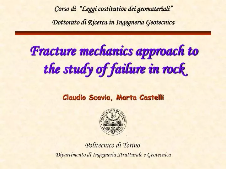
Corso di “Leggi costitutive dei geomateriali” Dottorato di Ricerca in Ingegneria Geotecnica. Fracture mechanics approach to the study of failure in rock. Claudio Scavia, Marta Castelli. Politecnico di Torino Dipartimento di Ingegneria Strutturale e Geotecnica. Index. Introduction

E N D
Corso di “Leggi costitutive dei geomateriali” Dottorato di Ricerca in Ingegneria Geotecnica Fracture mechanics approach to the study of failure in rock Claudio Scavia, Marta Castelli Politecnico di Torino Dipartimento di Ingegneria Strutturale e Geotecnica
Index • Introduction • Basic concepts of Linear Elastic Fracture Mechanics • Propagation criteria • Non linear Fracture Mechanics • Numerical modelling of cracked rock structures • The Displacement Discontinuity Method • Numerical simulation of experimental results • Application to slope stability
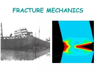
Introduction Since Coulomb (1776) the problem of failure in natural and man-made material have been approached on the basis of the traditional concept of Material strength This approach cannot explain some disastrous brittle failures and can be (depending on the scale) a great oversimplification of the crack initiation process Schenectady ship (1943) Tay bridge (Scotland, 1898)
Introduction The main cause of fracture initiation is the presence of defects in the material, which concentrate the stress at their tips Large natural defects (faults, joints…) exist in rock masses Example: progressive failure in slopes Fracture Mechanics makes it possible to take such phenomenon into account through a study of the triggering and propagation of cracks starting from natural defects or discontinuities
Introduction Main steps in Fracture Mechanics Analysis of the state of stress Evaluation of stress concentration Choice of a propagation criterion Definition of a methodology for the simulation of crack propagation • stable propagation • unstable propagation
Direct tension Indirect tension Axial splitting Shear band 1 s1 1 1 3 Modes of failure in rocks At the scale of the laboratory
Shear Direct tension Indirect tension Modes of failure in rocks At the scale of the rock mass
Index • Introduction • Basic concepts of Linear Elastic Fracture Mechanics • Propagation criteria • Non linear Fracture Mechanics • Numerical modelling of cracked rock structures • The Displacement Discontinuity Method • Numerical simulation of experimental results • Application to slope stability
Linear Elastic Fracture Mechanics • Elastic behaviour of the material • Inelastic behaviour of crack surfaces • Determination of stress concentration at the crack tip • fracture energy • stress intensity factor • Definition of the conditions for crack to propagate, through energetic or stress intensity balances
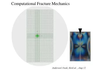
s s s circular hole elliptical hole crack 2b0 2b a a s s s smax smax = 3s smax = f(a, b) smax 3s s s s r r r Stress concentration
Condition for crack propagation elastic energy release rate surface energy 2g = fracture energy Gc fracture energy is a material characteristic which accounts for the energy required to create the new surface area, and for any additional energy absorbed by the fracturing process, such as plastic work Energetic approach (Griffith, 1921)
Tensional approach (Irwin, 1957) Crack propagation can be studied through the superposition of the effects of three independent load application modes mode I opening - loads are orthogonal to the fracture plane mode II slip - loads are tangent to the fracture plane in the direction of maximum dimension mode III tear- loads are contained in the fracture plane and act perpendicularly to mode II
Tensional approach • The state of stress in plane conditions (modes I and II) at a point P close to the crack tip is given as:
Tensional approach • For =0 i.e. for a point at a distance r along the line of the crack: y r ûy x q • For relative displacements û between the crack faces at a small distance x from the crack tip:
s r Tensional approach • stresses tend to infinity when r 0 • the Stress Intensity Factors K quantify the effect of geometry, loads, and restraints on the magnitude of the stress field near the tip
s 2b0 a s sy s r Meaning of the Stress Intensity Factors Example: crack of length 2a, located in a plate subjected to a uniform vertical tensile stress The vertical stress, y, around the crack tip is given by the theory of elasticity: The specific boundary conditions of the problem affect the value of y through a constant term KI which is given by:
Meaning of the Stress Intensity Factors • The value of K is representative of the stress field around the crack tip • for known geometrical characteristics of the specimens, it is possible to determine the critical value of K (toughness of the material) that will trigger propagation • A comparison between the experimental values of KC and the values computed at the tips of cracks makes it possible to establish whether or not they can propagate, provided that the behaviour of the rock material is assumed to be linear-elastic propagation criterion
Index • Introduction • Basic concepts of Linear Elastic Fracture Mechanics • Propagation criteria • Non linear Fracture Mechanics • Numerical modelling of cracked rock structures • The Displacement Discontinuity Method • Numerical simulation of experimental results • Application to slope stability
Propagation criteria open cracks: mode I propagation takes place in most brittle materials, and a Linear Elastic Fracture Mechanics approach is suitable for the simulation of the phenomenon, on the basis of the fracture toughness KIC (or fracture energy GIc) closed and compressed cracks: several mechanisms must be taken into account, and different criteria are to be chosen for the study of induced-tensile and shear propagation In some case it is necessary to resort to a non linear approach, depending on the extension of the zone of localized deformation
Open cracks (Erdogan & Sih, 1963) • cracks spread radially starting from their tips; • the direction of propagation, defined by an angle 0, is perpendicular to the direction along which the maximum tensile stress, (0), is found; • crack begins to spread when (0) reaches a critical value (0)C; • By expressing (0) and (0)C as a function of the stress intensity factors, the propagation criterion can be written in this form: where KIC is the material toughness
Open cracks (Erdogan & Sih, 1963) • For pure mode I: • For pure mode II:
KI > 0 KII = 0 KI < 0 KII 0 KI > 0 KII 0 KI = 0 KII 0 KI < 0 KII = 0 Open cracks
Closed cracks Induced-tensile propagation: Brittle phenomenon (mixed mode) The original crack is compressed, while the part that propagates is open and in a tensile stress field (Erdogan & Sih, 1963) KIC Shear propagation: (mode II) The original crack is compressed, and it propagates in compressive stress fields KIIC?
1 3 The meaning of fracture toughness in mode II (KIIC) is still under discussion Shear propagation criteria A controversial issue is whether or not it is possible to apply LEFM concepts to the analysis of shear failure Experimental evidence show that compressed cracks in brittle materials evolve along shear fracture planes only after a long process involving the formation of microcracks under tensile stresses, their propagation and coalescence in large-scale shear progressive failure The propagation is accompanied by considerable energy dissipation due to friction
Fracture toughness: mode I Experimental determination Suggested methods (ISRM, 1988) Short rod (SR) Chevron bend (CB)
D P t a0 a a1 W D/2 Short rod P load on specimen D diameter of short rod specimen W length of specimen h depth of crack in notch flank chevron angle t notch width a0 chevron tip distance a crack length a1 maximum depth of chevron flanks notch uncut rock or ligament
h P Support roller loading roller a a0 A D S L a CMOD Chevron bend uncut rock or ligament notch P load on specimen A projected ligament area L specimen length S distance between support points D diameter of chevron bend specimen CMOD relative opening of knife edges h depth of crack in notch flank chevron angle = 90° a0 chevron tip distance a crack length knife
When is a LEFM approach applicable? a zone of material exhibiting a non linear behaviour (process zone) always forms at the crack tips, where the actual evolution of stresses is bound to deviate from the theoretical elastic values only when this zone is small compared to the size of the structure, the actual evolution of stresses will still be governed by K and the Linear Elastic Fracture Mechanics procedure can be applied Extremely high stress values involved in the phenomenon of crack propagation:
Index • Introduction • Basic concepts of Linear Elastic Fracture Mechanics • Propagation criteria • Non linear Fracture Mechanics • Numerical modelling of cracked rock structures • The Displacement Discontinuity Method • Numerical simulation of experimental results • Application to slope stability
Non Linear Fracture Mechanics • Elastic behaviour of the material • Inelastic behaviour inside the process zone and on crack surfaces • Stress distribution does not present any singularity at the crack tip • stresses must be computed taking into account different constitutive models for intact material and the process zone • Definition of the conditions for the propagation of the crack and the process zone on the basis of material strength
Non linear Fracture Mechanics Process zone at the crack tip zone accompanying crack initiation and propagation in which inelastic material response is occurring The micro-structural process of breakdown near the crack tip can be interpreted by assuming that it gives rise to cohesive stresses, which oppose the action of applied loads
stress free inelastic elastic stress distribution stress distribution st dc Visible crack true crack process zone Non Linear Fracture Mechanics Open cracks (tension): the Cohesive Crack Model (Dugdale, 1960; Barenblatt, 1962)
real crack process zone p r r n real tip fictitious tip n r * G Non Linear Fracture Mechanics Closed cracks (compression and shear): the Slip-Weakening Model(Palmer & Rice, 1973) • A process zone is introduced at the crack tip, where the damage is concentrated • Here, a relation is assumed between relative displacement and shear stress • A residual shear strength r occurs when reaches a critical value * • = process zone extension • G= energy amount stored inside the process zone
Index • Introduction • Basic concepts of Linear Elastic Fracture Mechanics • Propagation criteria • Non linear Fracture Mechanics • Numerical modelling of cracked rock structures • The Displacement Discontinuity Method • Numerical simulation of experimental results • Application to slope stability
Numerical modelling of cracked rock structures Analysis of the state of stress and simulation of the propagation • Boundary Element Method (BEM) requires only the discretisation of the structure boundaries and hence it is suited to deal with problems characterised by evolving geometries Resort to numerical techniques for the analysis of cracked rock structures proves necessary because of the geometrical complexity of most application problems • Finite Element Method (FEM) Needs a re-meshing at each crack propagation step
n +Dn Ds = us(s, 0-) - us (s, 0+) Dn = un(s, 0-) - un (s, 0+) s +Ds 2a Numerical modelling of cracked rock structures Displacement Discontinuity Method (Crouch & Starfield, 1983) allows to simulate the crack as Displacement Discontinuity elements
s (j) n (N) bj n s (i) bi (1) The Displacement Discontinuity Method computer code BEMCOM influence coefficients of Ds(j) and Dn(j) on stresses or displacements over the i-th element known tangential and normal stresses or displacements acting on the i-th element unknown displacement discontinuities in the tangential and normal directions, in the centre of the j-th element
Open elements Tensile stress fields • Dn < 0 (opening) • s(i), n(i) = 0 Compressive stress fields • Dn> 0 (closure) • s(i), n(i) = 0
Closed elements Compressive stress fields • Dn = 0 • s(i), n(i) 0 s sr = n·tan Ks Ds No Displacement Discontinuities in the normal direction A tangential Displacement Discontinuity occurs if and when the available frictional shear strength is mobilised
Simulation of crack propagation (Scavia, 1995; Scavia et al., 1997) • open cracks Erdogan & Sih’s propagation criterion, based on the Stress Intensity factors calculation at the tip of the crack • closed cracks • induced-tensile propagation: Erdogan & Sih’s criterion • shear propagation: calculation of the stress field near the tip and its comparison with the Mohr Coulomb strength criterion • The load is applied in step, and the possibility of crack propagation is evaluated at each step. If such possibility is verified, a new element is added at the crack tip • Two kind of propagation may occur: • stable propagation may develop only if the load is increased • unstable propagation: develops without any load increment
t tp j* tr c* (Ds) tip element real crack t non-cohesiveprocess zone n cohesiveprocess zone Numerical implementation of the SWM Computer code BEMCOM (Allodi et al., 2002)
j c jp cp jr 0 * 0 c* Adopted slip-weakening laws • intact material (tip element): cp, p • real crack: c = 0, = r • process zone: linear variation of c and as a function of c* and * Cohesion (c) Friction angle ()
Index • Introduction • Basic concepts of Linear Elastic Fracture Mechanics • Propagation criteria • Non linear Fracture Mechanics • Numerical modelling of cracked rock structures • The Displacement Discontinuity Method • Numerical simulation of experimental results • Application to slope stability
Numerical simulation of experimental results The computer code BEMCOM has been used to simulate some experimental results through a LEFM approach: • Induced-tensile propagation in hard rock bridges (Castelli, 1998) Experimental work on concrete samples containing two open slits subjected to uni-axial compression • Shear propagation in soft rocks(Scavia et al., 1997) Experimental work on Beaucaire marl samples subjected to uni-axial compression in plane-strain conditions (Tillard, 1992)
Induced-tensile propagation (Castelli, 1998) Experimental work on concrete samples containing two open slits subjected to uni-axial compression Characteristic of the material Geometry and load configuration
longitudinal oblique horizontal Experimental results Stress-strain diagram Strain directions
Propagation trajectories Experimental Numerical
c7-c8 c5-c7 Shear propagation (Scavia et al., 1997) Experimental work on Beaucaire marl samples subjected to uni-axial compression in plane-strain conditions (Tillard, 1992) measured displacements (stereo-photogrammetry) Axial load-axial strain diagram
Numerical simulation • two initial notches, 2 mm long and inclined 28° to the vertical, are inserted at the upper corners of the specimen • onset of propagation occurs at an axial applied stress equal to 0.9 MPa = 28° l = 2mm