Download
1 / 24
240 likes | 261 Views
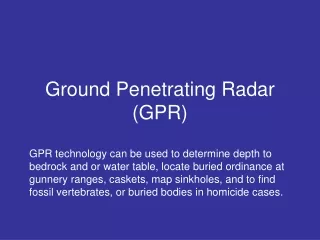
15th Int . Conf . Ground Penetrating Radar GPR 2014 June 30 - July 4, 2014, Brussels , Belgium. A new densely-sampled Ground Penetrating Radar array for landmine detection. L. Nuzzo , G. Alli, R. Guidi, N. Cortesi, A. Sarri, G. Manacorda IDS Ingegneria Dei Sistemi S.p.A.

E N D
15th Int. Conf. Ground Penetrating Radar GPR 2014June 30 - July 4, 2014, Brussels, Belgium A new densely-sampled Ground Penetrating Radar array for landmine detection L. Nuzzo, G. Alli, R. Guidi, N. Cortesi, A. Sarri, G. Manacorda IDS Ingegneria Dei Sistemi S.p.A. Via Enrica Calabresi, 24 - Loc. Montacchiello, 56121, Pisa (PI), Italy l.nuzzo@idscorporation.com allrightsreserved
Outline • INTRODUCTION • GPR in Humanitarian Demining • SYSTEM ARCHITECTURE • Overview of the GPR system • The antenna subsystem • The GPR array • EXPERIMENTAL RESULTS • Laboratory tests for antenna characterization • In-house tests of the GPR array • CONCLUSION allrightsreserved
INTRODUCTION TIRAMISU: Toolbox Implementation for Removal of Anti-personnel Mines, Sub-munitions and UXO Funded FP7 program (2012-2015) aiming to provide a modular integrated solution in humanitarian demining. 26 PARTNERS - 12 Countries COORDINATOR: Royal Military Academy of Belgium (Belgium) allrightsreserved
INTRODUCTION Densely sampled GPR array allrightsreserved
GPR in Humanitarian Demining • Wide variety of targets: from small shallow-buried AP mines to AT mines and deeply-buried large UXO (devices that sink deep with time in soft soils) • Wide variety of environments/soils, typically rural with overgrown vegetation • Wide variety of climatic conditions (arid and humid regions) and target status • Possibly weak electromagnetic anomaly due to: • Similar dielectric constant of the (low-metal) mine with the embedding soil • Soil compactness in post-conflict scenarios where targets have been lying for years • High electromagnetic absorption in moist/conductive soils • High clutter level in rocky/vegetated soils (stones, roots, moisture pockets) • High probability of detection is required for a wide range of environments and target types • Low false alarm rate is desirable for efficiency, though moderate false alarm rate can be tolerated • Automatic target detection (ATD) is desirable but not mandatory; an operator skilled in data analysis can be involved • Air-launched antenna array is desirable since ground contact is problematic on rough soil • Small arrays (~1m wide) may be mounted on a small remotely-controlled vehicle; larger arrays may be mounted on a bigger sensor-carrying vehicle and improve detection efficiency • GPR data recording and GNSS registration is essential for quality assurance and data fusion with other sensors allrightsreserved
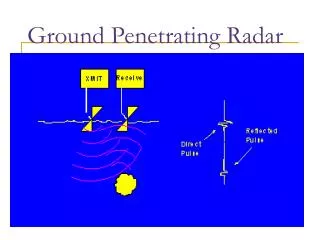
SYSTEM ARCHITECTURE • Densely sampled GPR array: develop a densely sampled, down-looking GPR imaging array with real time software for automatic detection of mines. • Challenges in landmine detection: • use of air-launched, rather than ground-coupled, antennas to prevent activation of the mines and facilitate surveying on rough terrains; • small spatial sampling along the array axis for detecting/resolving decimeter-sizeobjects. Schematic drawing of the GPR system for mine detection allrightsreserved
Overview of the GPR system • Vehicle-mounted GPR system similar to commercial, ground-coupled, dense arrays used in utility mapping, except for the use of purposely-developed air-launched antennas able to operate at a suitable distance (up to ~0.4 m) from the ground. Goal: increase the productivity with respect to hand-held sensors while maintaining the performance and the reliability of the results. The absolute coordinate measuring device (ACMD) provides absolute positioning reference for geo-referencing the GPR data for data fusion with data from a partner’s MD array. GPR system architecture and main interfaces with the other blocks of the close-in mine detection system allrightsreserved
The antenna subsystem • Requirements: • Ultra-wide band (UWB): >100% fractional bandwidth centered ~900 MHz as a trade-off between resolution of small targets (AP mines) and enough penetration for deep IED and UXO • Polarization: single linear polarization is sufficient for demining applications, since polarization is not an issue for spheroidal objects like mines • Antenna size and weight: small enough to permit the realization of a reasonably light (~50 kg) 1D array module with a large number of elements (~32) and sufficiently slim to allow dense packing with antenna spacing <5 cm • Height above the ground: the antenna should have optimal performances when operated as air-launched antenna at a distance not less than 30 cm from the ground surface (variable during the motion) • Radiation pattern: the antenna should have a small footprint on the ground surface in order to reduce problems related to surface clutter and low back-lobe and side-lobe level to prevent interference from above-surface reflections (e.g. from metallic parts of the vehicle) • Antenna design: • Proprietary EM Simulator based on the Method of Moments (MoM) allrightsreserved
The EM Simulation tool • Main features of the proprietary EM Simulator (ADF-EMS Framework) for modelling the antenna subsystem and analyzing its behavior in realistic conditions: • Method of Moments • Design of the radiating system (geometry and loading) • Antenna movement • Ground roughness allrightsreserved
Antenna simulation • Upgrading of a proprietary EM Simulator (ADF-EMS Framework)based on the Method of Moments (MoM) to assist the antenna design. • Intensive parametric analysis for optimizing its performances in the chosen frequency range. X-Y plane Isometric view of a resistively-loaded Vee dipole (RVD) antenna Simulated near field (dBV/m) of Vee dipole without (top) and with resistive loading (bottom) allrightsreserved
The GPR array • LUCIFER array (fc=900 MHz) • 450-1350 MHz UWB • 31 active channels • Dense spatial sampling: • 4 cm crossline • 1÷4 cm inline • >50 cm penetration in sand • High acquisition speed (up to 1400 scans/s @ 512 samples/trace) allowing a towing speed up to 6.5 km/h (1.8 m/s) • Width: 134.0 cm • Length: 51.3 cm • Height: 65.3 cm • Weight: ~60 kg The LUCIFER prototype allrightsreserved
EXPERIMENTAL RESULTS • Laboratory tests for antenna characterization • Measurements by a vector network analyzer (VNA) of the main antenna parameters (antenna impedance, E-plane and H-plane radiation patterns, boresightgain) • In-house tests of the GPR array • Calibration tests of the array: • on a metal plate assumed as Perfect Electric Conductor (PEC) • toward the sky • Tests of the array over controlled own test sites to assess the correct functionality of the various constitutive parts and identify potential problems, either: • manually towed • using mechanical scanners • mounted on different vehicles • Tests of the array over own test sites with mine simulants to assist the development of the signal processing software • Field trials • Pre-validation trials at the Belgian SEDEE-DOVO dummy minefield planned in July 2014. • Field-trials of the integrated close-in detection system at Croatian dummy minefields planned in Spring-Summer 2015. allrightsreserved
Laboratory tests • VNA measurements: • nearly flat, real impedance in the 0.5 ÷ 3 GHz frequency band; • ~1.4 GHz wide band (at -3 dB) from 0.8 GHz to ~2.2 GHz centered at 1.5 GHz; • antenna beamwidth (at -10 dB) ~60° in the E-plane and ~100° in the H-plane with good front-to-back lobe ratio ~1.4 GHz Gain vs Frequency of the RVD prototype Impedance of two RVD prototypes allrightsreserved 0.35 0.8 2.25 2.75
Laboratory tests • Tests over a perfect electric conductor (PEC): • ~900 MHz (from 500 to 1400 MHz) effective bandwidth at -3 dB • 950 MHz central frequency and 850 MHz peak frequency. • Bandwidth adequate for the application with low-frequency content essential for preserving adequate depth penetration (~0.5 m) in unfavorably conductive soils. ~900 MHz 40 cm PEC allrightsreserved
In-house tests • Tests of the array over controlled own test sites: • manually towed • using mechanical scanners • mounted on different vehicles allrightsreserved
In-house tests ~ 50 cm T9a&b Hydrological/stratigraphic interface T8 > 1m penetration in favorable terrains T7t T6 sand/gravel T5 T1 T2 T3 T4 T5 T6 T7t T8 T9a&b T10 Early tests on a controlled test site with buried pipes (April 2013) B-scan after cross-coupling removal and cross-section of the buried pipes allrightsreserved
In-house tests Ability to detect decimeter-size objects in favorable terrains Data Processing: B-scan (i.e. depth-slice) of transversal ½” metal pipe and Ø 5cm metal sphere buried at <40 cm depth in homogeneous sandy soil after pre-processing B-scan after array focusing C-scans (i.e. top-view) at a given depth after focusing 2D plan view of ATD at raster stage pipe sphere pipe sphere allrightsreserved
Data Processing Second stage First stage CFAR Classification First stage: Pre-processing (CC removal, GB tracking and removal, Sensitive Time Control), Imaging (velocityestimation and Migration), AnomalyDetection Second stage: FeatureExtraction and Classification allrightsreserved
In-house tests Test of the algorithm for Ground-Bounce tracking ad removal B-scan of selected channels GPR-derived ground morphology and map of superficial anomalies allrightsreserved
In-house tests D2 D1 D1: fiberglass @ 11 cm depth D2: metallic @ 9 cm depth D1 D2 B-scan after pre-processing & STC False alarms 2D anomaly map D1 D2 Test with AT mine simulants (Ø: 19 cm, H: 7 cm) in gravelly/loamy soil allrightsreserved
Work in progress • System integration for field trials • Improvement of the real-time SW • Vehicle integration with the LOCOSTRA tractor (Pierre/DIME) • Integration with positioning & communication system (dGPS, TCP-box developed by partners of the Tiramisu consortium) • LOCOSTRA: Low-cost tractor-based platform modified to host: • an industrial dual remote control with maximum control distance >100m • a light armouringand innovative blast resistant wheels • agriculture derived implements • close-in-detection tools allrightsreserved
Work in progress • System integration for field trials • Improvement of the real-time SW • Vehicle integration with the LOCOSTRA tractor (Pierre/DIME) • Integration with positioning & communication system (dGPS, TCP-box developed by partners of the Tiramisu consortium) • Early results: • No significant EM interference of the remote control in the useful GPR band • Air reflections from the metallic parts of the vehicle or nearby obstacles efficiently attenuated by the use of radar absorbing material (RAM) allrightsreserved
Conclusion • A new densely-sampled GPR array for landmine detection has been realized within the FP7-funded research project TIRAMISU. • It is based on purposely developed air-launched antennas designed to be packed in a dense array and also optimized for deep penetration. • The preliminary results obtained so far are quite encouraging with regard to the requirements for humanitarian demining. Further tests in controlled environment and in operational scenarios will give valuable clues for improvements and refinements of the array. They will also give insights for fine tuning the processing software which is currently being developed. • Technological improvements are envisaged in the following areas: • Increase frequency and bandwidth for higher resolution at shallow depth • Acquisition speed, real-time data processing and automatic target detection (ATD) • Data fusion of information coming from GPR and other sensors (e.g. metal detector array). allrightsreserved
ACKNOWLEDGMENT The research leading to these results has received funding from the European Community’s Seventh Framework Programme (FP7/2007-2013) under grantagreement n° 284747, project TIRAMISU. http://www.fp7-tiramisu.eu allrightsreserved