Download
1 / 28
730 likes | 1.44k Views
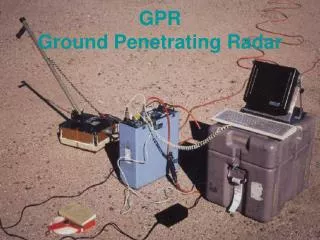
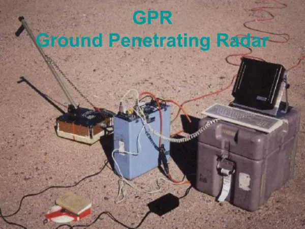
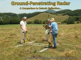
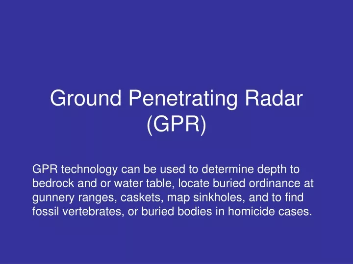
Ground Penetrating Radar (GPR). GPR technology can be used to determine depth to bedrock and or water table, locate buried ordinance at gunnery ranges, caskets, map sinkholes, and to find fossil vertebrates, or buried bodies in homicide cases. GPR.

E N D
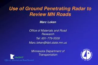
Ground Penetrating Radar(GPR) GPR technology can be used to determine depth to bedrock and or water table, locate buried ordinance at gunnery ranges, caskets, map sinkholes, and to find fossil vertebrates, or buried bodies in homicide cases.
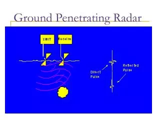
GPR isa reflection technique that requires very low power. It is a time-domain impulse radar, and transmits broad bandwidth pulses into geologic materials. A time-domain radar acts as a sounding device similar to depth finders in boats. A short pulse in the frequency range of 10 - 1000 Mhz is used. The propagation of the pulse is controlled by the relative dielectric permittivity (dielectric constant, r) which is dimensionless, relative magnetic permeability (r), and the conductivity () of the subsurface. Dielectric conduction takes place in poor conductors and insulators, which have no free carriers, by slight displacement of electrons with respect to their nuclei. (Dielectric constant: A measure of the capacity of a material to store charge when an electric field is applied.)
Dielectric constant or the relative Dielectric Permittivity (r) • the dimensionless ratio of the permittivity (), i.e. the ratio of the electric displacement (D) to the electric field (E) of the material to that of free space (o) • o = 8.9 x 10⁻¹² coul/nt-m2
The velocity of a radar-wave can easily be estimated for a particular material by taking the square root of its dielectric constant (V = .3/r m/ns); the .3 is because radar-waves are referenced to the speed of light in air or in vacuum (.3 m/ns). Dielectric constants for most dry geologic materials range from 4 (quartz sand) to 7 (shales and carbonates). Water, however, has a dielectric constant of 81 at 20oC and radically alters the velocity of the radar-wave traveling through materials and can cause serious errors in estimating depth. Saturated quartz sands will have a dielectric constant of up to 30; granite will rise from 5 to 7 as it becomes wet; dry soils will rise from 8 to about 20 as they become wet.
Radar waves can generally resolve objects on the order of one-half to one-fourth wavelength and the wavelength of the radar-wave decreases as it encounters higher dielectric material with depth so the resolution increases.
Attenuation or loss of radar energy is a complex function of the dielectric and electrical properties of the media through which the radar signal is traveling. Attenuation factor is controlled by the conductivity (), the relative magnetic permeability (r), and the relative dielectric permittivity (r) of the medium as well as the frequency of the signal itself.