Download
1 / 14
140 likes | 265 Views
Operation Transistor. Matthew Ladew Philip Hart Jenniffer Estrada. Stage 1 Amplifier. Pmos transistors MP1 and MP2 ensure identical biasing drain currents for MND1 and MND2 Active load- behaving as a current-stable nonlinear resistor Act similarly to a current mirror

E N D
Operation Transistor Matthew Ladew Philip Hart Jenniffer Estrada
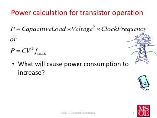
Stage 1 Amplifier • Pmos transistors MP1 and MP2 ensure identical biasing drain currents for MND1 and MND2 • Active load- behaving as a current-stable nonlinear resistor • Act similarly to a current mirror • Nmos transistors MND1 and MND2 act as differential pair • Common mode and differential mode can be considered separately using superposition • Differential gain is given by: • Current Source • Uses a current mirror to supply a constant dc biasing current to differential amplifier Fig. 1: Stage one, the differential amplifier and current source Gain of stage one: 29 V/V
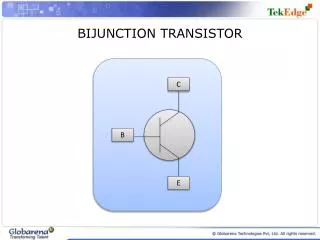
Current Mirror • MN2 matches reference current provided by MN1 • Since MN2 has the same gate-source voltage, the drain current must be identical • Potentiometer Rref adjusts this gate-source voltage to obtain desired reference current • As long as MN2 remains in saturation, drain current will be mirrored Fig. 2. Current mirror schematic
Stage 2 Amplifier • Pmos MP3 added in common source configuration • Inverting gain • Drain current, IDP3, determined by ratio: (W/L)P3/(W/L)P1 • MP3 not doubled in width: only one transistor in the CD4007 chip used • Nmos MN3 supplies a mirrored source current • Drain current, IDN3, determined by (W/L)N3/(W/L)N1 • Good match occurs when drain currents IDP3 and IDN3 are identical, which results in DC bias voltage of zero at output VO2 • Significant mismatch between transistors MP1 and MP3 resulted in poor gain, we eventually replaced MP1 to achieve a much higher gain Fig. 3 Two stage amplifier with second stage, common source amplifier on the right side of the schematic Gain of stage two: -35 V/V
Stage 3 Amplifier • Push pull structure added by MP4 and MP4 • Adds low output impedance • Crossover distortion minimized by correct value of RGG • Potentiometers RGG and Rref were tuned in succession several times so that VGG > 1.1(Vtn + ⎟Vtp⎜) and VO = 0. Fig. 4 Complete three stage amplifier, with third and final stage Stage 3 Gain: 1800 V/V
Screenshot- Third Stage Without RGG With RGG Third stage: Yellow trace is Vo2+, Green is Vo, purple is Vo2+ - Vo; this demonstrates the effect of RGG on the crossover distortion.
Miller Capacitor • Miller capacitor added between outputs of first and second stages • Adds a pole to the bode plot to place the 3db point to a lower frequency • Prevented feedback oscillation
Non-Inverting Op-Amp • R1 = 2Kohm • R2 = 200ohm • Vin at non-inverting input V2, R2 connected from inverting input V1 to ground
Inverting Op-Amp • Rf = 2Kohm • Ri = 200ohm • Non-inverting input at V2 grounded, Ri connected between inverting input V1 and Vin