Download
1 / 9
90 likes | 205 Views
Control of TPC Pulsers. General Calibration pulser Gating pulser Power supply control Pulser monitor Status. General. Gate pulser : open/close gating grid - absorbs electrons from drift region - absorbs ions from amplification region

E N D
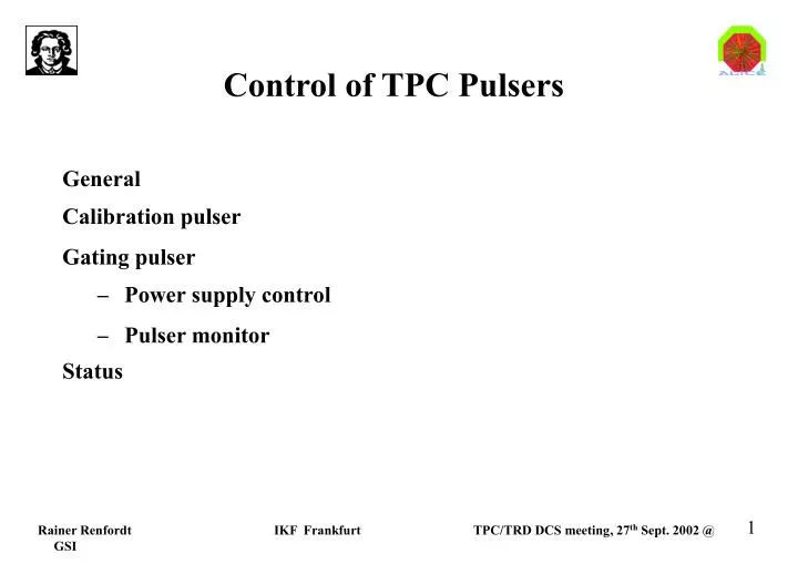
Control of TPC Pulsers General Calibration pulser Gating pulser • Power supply control • Pulser monitor Status
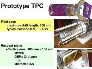
General Gate pulser: open/close gating grid - absorbs electrons from drift region - absorbs ions from amplification region Calib. Pulser: injects charge into PASAs - electronics test - electronics gain calibration Pulsers not accessible Goal: - all vital functions monitored - critical voltages remotely controlled Gate pulser Calib. pulser
Calibration pulser: schematics In control room In pit (on both sides of the TPC) (40 m distance)
Calibration pulser (2) 2 crates 6U ground free setup: everything (or at least the output stage) floating one point foreseen for possible ground connection 1 backplane distr. of power distr. of analog reference signal distr. of control signals for switching of channels (6 lines ?) 1 power supply:+-5V, +-12V status indication by LEDs 1 control board CAN-bus or Profibus interface FPGA DAC readout of supply voltages via ADC inputs (clock, trigger) galvanically isolated which cables, which standard (LVDS, NIM ...) not clear yet 5 (7) driver boards BNC connectors, ground free 8 driver channels per board Uout max: 3V (?) at 50 Ohm channels switchable low noise status indication by LEDs
For TPC partition: - normal pulsing incl. parameter variation: - on/off - selection of readout chamber(s) - Amplitude - single/multiple pulses - calibration procedure: fixed sequence of amplitudes & recording (DAQ & tape) Calibration pulser: control ECS DCS - on/off - selection of readout chamber(s) - Amplitude - single/multiple pulses PC - Load new pulseshape 120 m profibus Pulser
-130 V +100 V -100 V 5V 9 V Gating pulser (NA49) Gate out 10x Pulser Pulser Pulser Trigger in
+100 V -100 V -130 V -130 V Controller Controller Gating pulser (Alice) Profibus Gate out Gating monitor voltage moitor 5V, 9 V Trigger in Pulser Pulser Pulser To next crate RS 232 RS 232
Gating pulser: control ECS For TPC partition: - normal gating on/off - monitor gating - monitor voltages DCS - monitor gating - set/monitor voltages Trigger Gating on/off Profibus RS232 Gating pulser
Status Calib. Pulser: - prototype exists: NIM module, FPGA, DAC - details about Profibus connection not defined yet (manufacturer, model) Gating pulser: - design for pulser itself exists (Danilo, Zagreb) - study started how to pick up gating signal and control switching (IKF) - survey for remotely controllable power supplies started (IKF) (Agilent has system with 8 modules, 200V, but: IEEE 488 control!)