Download
1 / 23
230 likes | 338 Views
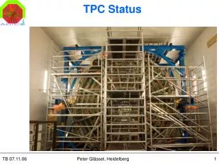
TPC Design. Howard Wieman CCAST Student Lecture. Topics. TPC what it does TPC How it works Electron drift in gas Wire chamber/pad readout. BRAHMS. PHOBOS. PHENIX. STAR. TPC. I will cover TPC technology, but examples will be for the STAR TPC at RHIC

E N D
TPC Design Howard Wieman CCAST Student Lecture
Topics • TPC what it does • TPC How it works • Electron drift in gas • Wire chamber/pad readout
BRAHMS PHOBOS PHENIX STAR TPC • I will cover TPC technology, but examples will be for the STAR TPC at RHIC • The TPC is the main detector in the STAR experiment
TPC what it does • Measures many of the charged particles radiating from the collision point • Measures momentum vectors of the particles. This is done by electronically recording high resolution space points along the particle path as it curves through a magnetic field • Determines the particle species from the density of ionization left by the particle as they travel through gas
TPC – How it works – 3D from 2D Path of ionization left by a particle radiating from the collision Electrons green Positive ions red • The TPC is basically an empty volume of gas with an electric field • High velocity particles leave a trail of ionization (electrons and positive ions) as they pass through the gas • The particles are detected using the released electrons they leave in their path • The electrons drift in through the gas driven by the electric field (typical drift velocities – centimeters per s) • The drifting electrons are detected at the end cap with a 2D array of detectors • Two dimensions of the path are obtained by the 2D pattern traced on the end cap • The third dimension is obtained from the arrival time, the time it takes the electrons to drift from the track creation point to the end cap detectors • The start time is know from the accelerator bunch timing or from fast detectors such as scintillators which detect the fast particles thus identifying the time of interaction • The end time is determined by the end cap array of detectors • The positive ions drift much slower ( ½ sec) than the electrons (10s of sec) • The positive ions are not detected but they do affect TPC performance – a subject to be addressed later in this talk E
Topics to be covered xxxxx • overview • 3D tracking with dE/dx for particle ID • generating the signal • track point reconstruction • limits on momentum resolution • multiple scattering • accuracy of track reconstruction • readout resolution • distortions in the electron drift path
More topicsxxxxxx • particle identification with dE/dx • limitations due to ionization fluctuations • front-end low noise electronics
The best way to learn about TPCs and other gas based detectors
An excelent reference on signal generation and readout elelectronics Ann. Rev. Nucl. Part. Sci. 1988. 38: 217
TPC Capability • Tracking, momentum reconstruction for 4000 charged particles in 0<|h|<1.8 • Dp/p = 1.5% low p, Dp/p = 3% at 10 GeV/c • Particle ID by dE/dx, 6.7%
Why we need a TPC • to get particle momentum and particle identification in a high track density environment one needs to over sample, i.e. lots of 3D pixels • the TPC provides by far the lowest cost per pixel of any detector • it does this by recording 3D space with 2D hardware
gas gain amplification at the anode wire on the sector avalanche in the high field region near the anode wire E = ~200 kV/cm
current induced in the wire as the avalanche positive ions drift away from the wire the “one over t tail” I(t) q(t)
charge induced on the pad plane surface by a line charge at the wire location D + a good measure of the true surface charge generated by the avalanche positive ions x
pad signal as a function of distance between avalance and pad center(pad response function) 0 x
extracting track position • the avalanche position is extracted assuming a gaussian pad response function if the cluster is narrow (~3 pads wide) • i.e. the track is close to perpendicular to the wires (a = ~0) • a weighted mean is used for wider clusters where a is larger
sources of error in the hit position determination • electron cloud width due to diffusion while drifting • tan(a) effect due to clustering or non uniform deposition of charge along the track • EXB term in the drift velocity as the electrons approach the anode wire • electronic noise of the amplifier • Total rf direction error in STAR TPC: a 20:1 signal/noise center pad ~ 500 mm
gating grid • reduces drift distorting space charge by preventing avalanche positive ions from reaching the drift volume • reduces wire aging by preventing electrons from non-trigger events from reaching the MWPC • symmetric + - on alternate wires largely prevents induced signals on the wires and pads
measuring momentum • tracking in a magnetic field • sources of error • multiple coulomb scattering • errors in hit reconstruction • global distortion in the electron drift path