Download
1 / 5
50 likes | 145 Views
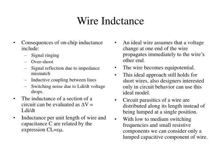
Consequences of on-chip inductance include: Signal ringing Over-shoot Signal reflection due to impedance mismatch Inductive coupling between lines Switching noise due to Ldi/dt voltage drops. The inductance of a section of a circuit can be evaluated as V = Ldi/dt

E N D
Consequences of on-chip inductance include: Signal ringing Over-shoot Signal reflection due to impedance mismatch Inductive coupling between lines Switching noise due to Ldi/dt voltage drops. The inductance of a section of a circuit can be evaluated as V = Ldi/dt Inductance per unit length of wire and capacitance C are related by the expression CL=ε. An ideal wire assumes that a voltage change at one end of the wire propagates immediately to the wire’s other end. The wire becomes equipotential. This ideal approach still holds for short wires, also designers interested only in circuit behavior can use this ideal model. Circuit parasitics of a wire are distributed along its length instead of being lumped at a single position. With low to medium switching frequencies and small resistive components we can consider only a lumped capacitive component of wire. Wire Indctance
This is a simple but yet effective model and widely used in digital design. There is a need to include the resistive as well as the capacitive components. We can lump the total wire resistance into a single R and the global capacitance into a single C. The lumped RC model is inaccurate for long interconnects. The RC network can enhance understanding of a distributed RC network. In order to evaluate the RC model we use the RC tree which has: Has a single input node S. Has all capacitors between a node and ground. Has no resistive loops Lumped C Wire Model Vout Cwire Driver Vout RDriver CLumped Source
The resistive-capacitive (RC) model. R1 is the common resistance in the path. There is a unique resistive path between the source node S and any node i on the network A shared path resistance from the root node to nodes k and i is: The equation describes the common resistance from input to nodes i and k. The Lumped RC Model R2 2 R4 C2 1 S R3 4 R1 3 C4 Ri C1 i C3 Ci R2 R1 C2 R3 C1 C3
If we have a step input and if we assume that all nodes are initially at logic 0 we have: The Elmore Delay Model offers designers a quick estimate of the delay. To compute the time constant of a wire of length L, we partition the wire into N identical segments. Each segment has a length of L/N. The segment resistance becomes r(L/N). The segment’s capacitance becomes c(L/N). The above equation calculates the time constant of the wire using the Elmore Delay Model. For rL = R and cL = C we have the Lumped R and C. If there are numerous segments (N Large) the RC model approaches that of a distributed RC line with: The Elmore Delay Model
The delay of a wire is a quadratic function of its length i.e. doubling the length of a wire quadruples its delay. The lumped RC model underestimates the delay by 0.5 times. The Elmore Delay model only estimates the value of the dominant component. We have discussed briefly that the Elmore Model can be used to estimate the delay complex transistor netwworks. Find the voltage at node i? Find the response at node i with respect to time? As the number of segments in the network becomes large with sections becoming smaller we have: The Elmore Delay Model Vin rL Vj-1 rL Vj rL rL Vout Vj+1 cL cL cL cL Ij-1 Ij Ij+1