Download
1 / 13
2.38k likes | 5.41k Views
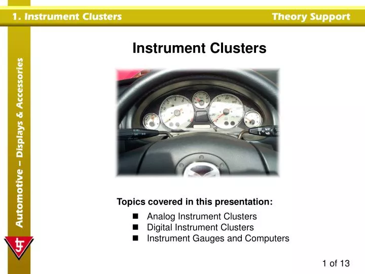
Instrument Clusters. Topics covered in this presentation: Analog Instrument Clusters Digital Instrument Clusters Instrument Gauges and Computers. Typical Analog Instrument Cluster. Tachometer. Speedometer. An instrument cluster displays the status of a vehicle’s systems. Rev limit.

E N D
Instrument Clusters • Topics covered in this presentation: • Analog Instrument Clusters • Digital Instrument Clusters • Instrument Gauges and Computers
Typical Analog Instrument Cluster Tachometer Speedometer An instrument cluster displays the status of a vehicle’s systems. Rev limit The speedometer is usually situated in a prominent position. Pointer Odometer It has a pointer that lines up with numerical values, which indicate vehicle speed in miles per hour (MPH). The speedometer also has an odometer to measure distance traveled. The tachometer displays engine speed in revolutions per minute (RPM). The rev limit (red area) indicates the maximum engine speed allowed, before damage can occur.
Typical Analog Instrument Cluster The fuel gauge displays the amount of fuel that is left in a fuel tank. Fuel quantity is measured in gallons. The temperature gauge displays engine coolant temperature. Temperature gauge Warning lamps Fuel gauge The gauges usually have a symbol to represent their function. Warning lamps are usually positioned around the perimeter of an instrument cluster. They may have red, green, blue or orange lenses. They are used to indicate system information such as oil pressure, parking brake, battery status, direction indication, hi beam, ABS, choke, etc.
PCB Typical Instrument Cluster Construction The instrument cluster is usually made of plastic and is held in position with screws. Instrument housing The front of the instrument cluster is protected by a transparent cover or lens. Speed, fuel and temperature gauges The instruments are fitted into, or are part of, the instrument housing. Support housing They are aligned / secured in place by a support housing that may also be a fascia with indication markings. Transparent cover or lens A printed circuit electrically connects components in the instrument cluster. Display illumination bulbsare often inserted from the rear.
Mechanically Driven Analog Speedometer The speedometer cable links between the speedometer head and the transmission housing. Speedometer head Flexible inner cable It has an inner cable that is a flexible wire with a drive gearon one end. It moves within a stationary outer housing. Outer cable housing When a vehicle is moving, it transfers motion through a gear linkage and rotates the speedometer inner cable. Cable inner wire and gear Drive gear Transmission housing At the speedometer head in the instrument cluster, a small magnet rotates. The resulting magnetic force moves the speedometer pointer.
Computer (ECU) Trigger wheel Analog or digital display Speed sensor Transmission housing Electronically Driven Speedometer The transmission housing contains an output shaft with a trigger wheel. A vehicle speed sensor is positioned next to the trigger wheel. When a vehicle is moving, the sensor produces a signal that relates to vehicle speed. Analog signal The computer (ECU / BCM) processes the input signal and converts the information into drive signals, for either analog or digital speedometers. Some analog systems do not use a computer. The frequency of the incoming signal is converted to a voltage, which is used to drive a stepper motor that deflects the pointer.
Ignition Coil Driven Analog Tachometer When an engine is running, the primary winding of the ignition coil is switched on and off to produce a spark. Tachometer Battery The switching rate is proportional to engine speed. Switching / ignition pulses Ignition switch The tachometer is connected to the minus (switching) terminal of the ignition coil. Coil switching device Ignition coil The switching pulses trigger the analog pointer in the tachometer to display engine speed in revolutions per minute (RPM).
Analog tachometer Analog or digital drive Analog signal Trigger wheel Speed sensor Computer (ECU) Digital tachometer Sensor Driven Analog/Digital Tachometer The crankshaft is fitted with a trigger wheel, which rotates while the engine is running. A speed sensor is positioned nextto the trigger wheel. It produces a signal that relates to engine speed. The computer (ECU / BCM) processes the input signal and converts the information into drive signals, for either analog or digital tachometers.
Warning/status lamps Fuel consumption Climate control Main display Tachometer Typical Digital Instrument Cluster The digital instrument cluster is lightweight and easy to read. It can have digital displays for speed, fuel level, climate control, distance traveled etc. There will also be lamps for warning / vehicle status, and direction indication. The displays may be LCD, LED, or vacuum fluorescent. Incoming data is processed by the Body Computer Module (BCM).
Input stage Output stage Analog Digital/ switch Processing stage Typical Instrument / Body Computer (BCM) The instrument computer has three main stages of operation: • Input. • Processing. • Output. The input stage processes both analog and digital inputs. Some input devices require a reference voltage to function. This is provided by the BCM’s power supply. Analog voltages are converted to digital signals by the A/D converter and / or amplifier, ready for processing. Weak or noisy digital signals are conditioned, ready for processing.
Typical Instrument / Body Computer (BCM) Input stage The “brain” of the computer is the processing stage. Output stage CPU operation is controlled by a software program, stored in read only memory (ROM). The CPU stores input data in random access memory (RAM). Analog Digital/ switch It compares input data against expected data and switches appropriate output drivers. CPU Processing stage The output stage switches the required actuators.
Speaker Fuel level sensor Lamp 5V BCM Digital display Typical Body Computer Circuits Fuel Level Circuit The resistance of the fuel level sensor changes with fuel quantity. This causes a corresponding voltage change at the BCM’s analog input. The BCM processes the input data and produces an output signal to drive a digital or analog display. The BCM may also switch on a lamp, or use a speaker to warn the driver that the fuel tank is nearly empty.
Speaker Lamp 12V Oil pressure switch BCM Typical Body Computer Circuits Oil Pressure Circuit When engine oil pressure is correct, the oil pressure switch is closed. The voltage at the BCM input is zero. When engine oil pressure is too low, the oil pressure switch is open. The voltage at the BCM input is 12V. The BCM will switch on a warning lamp or speaker, when 12V is measured at its input.