Download
1 / 19
190 likes | 198 Views
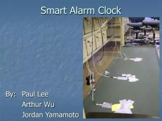
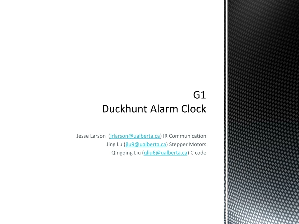
G1 Duckhunt Alarm Clock. Jesse Larson ( jrlarson@ualberta.ca ) IR Communication Jing Lu ( jlu9@ualberta.ca ) Stepper Motors Qingqing Liu ( qliu6@ualberta.ca ) C code. The Motivation. Imagine this: It’s EARLY in the morning, and your alarm sounds.

E N D
G1Duckhunt Alarm Clock Jesse Larson(jrlarson@ualberta.ca) IR Communication JingLu (jlu9@ualberta.ca) Stepper Motors QingqingLiu (qliu6@ualberta.ca) C code
The Motivation Imagine this: It’s EARLY in the morning, and your alarm sounds. How many of us secretlywish we could do this to our alarm clock Our Functionality Goal: To build an alarm clock that is capable of waking you up, and is fun to turn off. Making it somewhat nicer to wake up. The Idea: Make a sleeper perform simple and fun game to shut off the alarm clock
What our simple game is loosely based on If any of you remember this one… We hope to achieve a more realistic version
Design: General Structure of the Alarm clock Ceiling of the room Stepper motor Stepper motor 2 x 4 DE2 Board and Pulley and Pulley Infrared receiver Speaker Infrared Transmitter Strong fishing line Sensor bar. cleverly disguised as a duck What you will use to shut off the alarm Infrared Receiver Infrared Shotgun Transmitters
Design:General Behavior& Functionality Functions like a normal alarm clock except… The only way to shut off the alarm is to shoot the sensor bar 3 times. The reason for 3 hits is to break ties as we plan on having a “his” and “hers” gun for the alarm, encouraging a sense of competition and fun as the alarm clock can distinguish between the two guns announcing the winner after the alarm is shut off. Once the sensor bar has been shot down by the infrared guns, the sensor bar is safely retracted to its resting place on the roof where it will enter a low power state.
Design:The Sensor bar (duck) diagram 38 kHz IR signal 38 kHz active low IR receiver IR LED NAND gate 56 kHz clock 56 kHz IR signal
Design:The Gun (DE0) Diagram On/Off switch Load switch Trigger switch Send_Burst_Component ID switch Send_1_component Send_0_component IR LED 38 KHz Clock
Design:DE2 diagram ON-CHIP MEMORY SDRA LCD Screen Nios_II Seven Segment RESET 2bit Avalon MM Slave Signal decoder Motor Controller PWM Generator Peripheral Motors IR Receiver
Software Diagram: C Project -record and calculate the position of “duck” on x axis and y axis -generate acceleration for x axis and y axis -test whether the acceleration is safe -when a reset signal is received, bring up “duck” to original position SPEAKER VHDL -send a signal to turn on/off the speaker STEP MOTOR DE2 BOARD VHDL -realize the controlling of step motors VHDL -process signal and send gun ID RECEIVER
Design Calculation Variables: accelerationa_x, a_y current position x_curr, y_curr safedistance: 0.9-x_curr, 0.4-y_curr Moving range (2.0m*1.0m) y Safearea (1.8m*0.8m) Safe distance (x_curr, y_curr) x 0
Design Calculation Generatedrandomacceleration: a_x_generated, a_y_generated Saftacceleration: a_x, a_y Function to test the generatedacceleration a_x=2((0.9-x_curr)-Vx)/t^2 a_y=2((0.9-y_curr)-Vy)/t^2 • If((a_x<=a_x_generated)|| • (a_y<=a_y_generated)) • { a_x==a_x, a_y==a_y} else • { regenerated new accelerations } y 0 x
Sample code Define a motor controller: entity stepper_motor is port ( phase : out std_logic_vector (3 downto 0); direction : in std_logic; clk : in std_logic; reset_n : in std_logic; ); end stepper_motor;
Sample code architecture st of stepper issignal step_count :std_logic_vector ( 2 downto 0); begin process (rst,clk) begin if rst = '0' then step_count <= "000"; else if clk'event and clk = '1' then if direction = '1' then step_count <= step_count +1 ; elsif direction = '0' then step_count <= step_count -1 ; end if; end if; end if; -- end if; end process; process (step_count) begin case ( step_count) is when "000" => phase <= "0001"; -- 0 when "001" => phase <= "0011"; -- 1 when "010" => phase <= "0010"; -- 2 when "011" => phase <= "0110"; -- 3 when "100" => phase <= "0100"; -- 4 when "101" => phase <= "1100"; -- 5 when "110" => phase <= "1000"; -- 6 when "111" => phase <= "1001"; -- 7 when others => phase <= "0000"; end case; end process;end;
Challenges: 1. Deciding on the “best way” to implement the IR game aspect of the clock 2. Finding useable parts: - IR receivers need to have a significant range and must be feasible to connect to, only the most common frequency modulation (38kHz) is available on break out boards. We need two IR links with no cross talk if the sensor bar is to remain a simple relay. very few in stock available receivers meet this requirement. 3. Verifying that the “duck” is actually in the safe communication area
Test Plan Confirm the area of the IR communication links, adjust the safe area size if needed. Motor and Duck: limit the roaming area to inside the safe communication area. Test that all voltage suppliers have proper output, especially for the battery powered sensor bar. Test that the speaker is loud enough to wake someone up. Test the ranges and bounds of the functions.
Future Application Notes How to program a DS1077 as a stand alone oscillator (133 kHz down to 16.2 kHz) How to implement a custom IR communication protocol.
Features to Add/Remove Possible options to remove: 1. Remove the alarm clock function; it can just be a simple game. 2. Remove the two player aspect of the game, make only one shotgun. Possible options to add: 1. Create a friends flight server for the pattern of the duck. Meaning that your alarm clock will fly the same path as your friends duck hunt alarm clock at a different house. Both yours and your friends’ alarm clock will record the time it took each of you to shoot your alarm clock. Fastest times can then be posted at the end of each day encouraging a sense of competition amongst friends to wake up and shoot the clock faster than your friends. 2. Add a third stepper motor to make the sensor bars movement more stable. 3. Add a magnetic contact to dock the sensor bar, so it can enter a low power state. 4. Add a web interface to set alarms for convenience.