Download
1 / 72
730 likes | 810 Views
The ATLAS Trigger and Data Acquisition System An historical overview. Fred Wickens representing ATLAS TDAQ But with some personal commentary SLAC – 16 Nov 2010. Health Warning. This talk has been prepared at relatively short notice

E N D
The ATLAS Trigger and Data Acquisition SystemAn historical overview Fred Wickensrepresenting ATLAS TDAQ But with some personal commentary SLAC – 16 Nov 2010
Health Warning • This talk has been prepared at relatively short notice • insufficient time for me to check that details are totally up-to-date with the appropriate experts. • Some statements are my own opinions/recollections • may not be agreed by other ATLAS TDAQ participants. • Some slides have been stolen from other public talks on ATLAS, any errors of interpretation or detail are entirely mine • If you wish to know more details of the system see talks given at various recent conferences – especially CHEP2010, e.g. talks by Nicoletta Garelli and Ricardo Goncalo ATLAS TriggerDAQ
Outline The talk will describe the ATLAS Trigger Data Acquisition system,focusing mainly on the DataFlow and HLT Framework. Describing how it evolved, what it is now, its performance and some perspectives for the future. • Introduction • Including a Description of the problem as it appeared in 1994 when the ATLAS Technical Proposal was written • The history of how the system evolved • Noting some of the key architectural and implementation decisions • The history of how the system evolved • Noting some of the key architectural and implementation decisions • How it works • The performance achieved in 2010 • Future Challenges • Summary ATLAS TriggerDAQ
Introduction ATLAS TriggerDAQ
The ATLAS Detector Large angular coverage: ||<4.9; tracking in||<2.5 Inner detector ~100M Channels Pixels, Si-strips and Transition Radiation Tracker Calorimeters – O(100K) Channels Liquid Argon electromagnetic; Iron-scintillating tile hadronic Outer Muon Spectrometer ~ 1M Channels Magnets: Inner Tracker 2T solenoid Muons 4T air-core toroids 5 Fred Wickens, RAL - Seminar at SLACLHC Days in Split - 4 Oct. 2010 ATLAS TriggerDAQ
Physics rates at the LHC 7 TeV • At LHC Physics of interest is small fraction of total interaction rate • b-physics fraction ~ 10-3 • t-physics fraction ~ 10-8 • Higgs fraction ~ 10-11 • At 14 Tev and Luminosity 1034 • Design energy + Luminosity • Total interactions 109 sec-1 • b-physics 106 sec-1 • t-physics 10 sec-1 • Higgs 10-2 sec-1 ATLAS TriggerDAQ
The LHC and ATLAS • LHC design has • Energy 14 TeV • Luminosity 1034 cm-2s-1 • Bunch separation 25 ns (bunch length ~1 ns) • This results in • ~ 23 interactions / bunch crossing • ~ 80 charged particles (mainly soft pions) / interaction • ~2000 charged particles / bunch crossing • Produces ~PetaByte/s in detector (A stack of CDs a mile high!) • ATLAS Technical Proposal assumed: • Event size of ~1MB • Level-1 Trigger rate of ~100 kHz • Hence data rate into DAQ/HLT ~100 GB/s • Acceptable rate to Off-line ~100 MB/s ATLAS TriggerDAQ
Experiment TDAQ comparisons ATLAS TriggerDAQ
Time Line • 1994 Dec – ATLAS Technical Proposal • First physics assumed in 2005 • 1998 June – Level-1 Technical Design Report • 1998 June – DAQ, HLT and DCS Technical Progress Report • 2000 March – DAQ, HLT and DCS Technical Proposal • 2003 June – DAQ, HLT and DCS Technical Design Report • First physics now assumed in 2007 • 2005 – Detector Commissioning no central DAQ • 2006 – Detector Commissioning with central DAQ • 2007 – Start combined Cosmic running • 2008 Sept – few days of LHC running + more Cosmic running • 2009 Nov – LHC re-start at 900 GeV • 2010 Mar – LHC starts running at 7 TeV (3.5 on 3.5) ATLAS TriggerDAQ
Sociology • The ATLAS TDAQ community comprises a very large number of people and many institutes, only a few people at most institutes • L1 TDR – 85 people from 20 institutes • DAQ/HLT/DCS TP – 197 people from 45 institutes • DAQ/HLT/DCS TPR – 211 people from 42 institutes • DAQ/HLT/DCS TDR – 228 people from 41 institutes • Current • TDAQ Author list – 574 people from 105 institutes • TDAQ Institutes Board – 73 institutes • In addition, much of the early development of ATLAS was done in the context of the LHC R&D projects, which formed their own sub-communities, many wedded to particular views, potential solutions and even technologies ATLAS TriggerDAQ
Funding Issues • Complicated the picture even more: • Most of TDAQ was funded directly by participating Funding Agencies – not indirectly via the Common Fund • Consequently the number of Funding Agencies involved was • L1 – 7 FA’s (3 L1-Calo, 3 L1-Muon, 1 Central L1) • DAQ/HLT – Originally 15 FA’s + ~17% CF • Note subsequently 7 other FA’s have also contributed • DCS – 2 FA’s + ~40% CF • TDAQ has had to adjust to several major perturbations in funding • Loss of major part of CF to meet shortfalls elsewhere • Initial DAQ/HLT system had to be scaled back by ~50% as money needed to meet ATLAS cash-flow problems • But offset more recently by some additional contributions from new ATLAS collaborators ATLAS TriggerDAQ
Summary of the Problem • Thus ATLAS faced a problem: • Requiring system of unprecedented scale and performance • A number of candidate technologies existed which might support such a system, but no clear front runner - in terms of performance, cost, longevity and future evolution • A long timescale – time for technologies to evolve and solutions to emerge, but need to ensure a solution is in place • A large diverse community – many ideas but little agreement • A spectrum of approaches – from too abstract to too concrete • Development of the system was done gradually with various targeted studies: • To obtain a better understanding of issues • Strike a balance between abstract and concrete • Find a good solution, avoid searching for the “best” • Form a coherent community with consensus views ATLAS TriggerDAQ
History of how the System Evolved ATLAS TriggerDAQ
The ATLAS TP Architecture for DAQ/HLT • 3-Level Trigger • L1 uses selected coarse data from calorimeters and muon spectrometer • L1 latency ~2us • Data help in pipelines in detector front-ends • Avg L2 latency ~10ms • Event Building at ~1kHz • Data to storage/off-line at ~100Hz / ~100MB/s ATLAS TriggerDAQ
Possible Architecture Implementation of L2 • Uses RoI principle (see later) • During L2 decision time data stored in “LVL2 Buffers” • Parallel processing in Local Processors of data within each RoI from different detectors • Results from different detectors and different RoI’s combined in a Global Processor ATLAS TriggerDAQ
Possible Overall DAQ/HLT Implementation • Much of the thinking still based on custom h/w • VMEbus crates • DSP’s or FPGA’s for L2 Local • Special processor boards with micro-kernel for L2 Global • Various high speed interconnects suggested: Fibre Channel, HIPPI, ATM, SCI • Although was recognised that commodity h/w might become available for some parts ATLAS TriggerDAQ
Some key choices in the TP Architecture - 1 • Uniformity from the level of the ROL (Read-Out Link) • The read-out of each detector up to the output of the Read-Out Driver (ROD) is the responsibility of the detector group. • Although there are some commonalities there are major differences across the ROD’s • Separation of the ROD’s and the “Read-Out Crates”(now Read-Out System - ROS) • This simplified decision making, and also greatly simplified stand-alone detector and TDAQ commissioning and debugging. • The separation continues to give considerable operational advantages • But it has been noted that combining these units could lead to cheaper hardware and more flexible solutions. ATLAS TriggerDAQ
Some key choices in the TP Architecture - 2 • Separation of the ROD crates of different detectors into a small number (~15) of fixed TTC zones(Timing Trigger and Control – a real-time high precision timing system for synchronisation and transport of small data packets) • The DAQ (and EF part of HLT, but not L1 or L2) can also be partitioned to allow concurrent independent operation of different detectors. • This supports parallel independent calibration or debugging runs of different detectors. • The LVL1 architecture essentially as built (See below) • Although there were further developments • some technology changes (e.g. fewer ASIC’s, more FPGA’s) • max rate reduced from 100 to 75 kHz • to reduce the cost of some detector electronics • The RoI Principle • See next slide ATLAS TriggerDAQ
Regions of Interest • The Level-1 selection is dominated by local signatures (i.e. within Region of Interest - RoI) • Typically, there are 1-2 RoI/event • Can obtain further rate reductionat Level-2 using just data withinthe Region of Interest • E.g. validate calorimeter data at fullgranularity • If still OK check track in inner detector • Emphasis on Reducing network b/w and processing power required • Thus reduced the demand on the technology, but stronger coupling between Trigger and DataFlow ATLAS TriggerDAQ
~ 100 Hz Physics ~ 100 MB/s ARCHITECTURE Trigger DAQ 40 MHz ~1 PB/s(equivalent) Three logical levels Hierarchical data-flow LVL1 - Fastest:Only Calo and MuHardwired On-detector electronics: Pipelines ~2 ms LVL2 - Local:LVL1 refinement +track association Event fragments buffered in parallel ~10 ms LVL3 - Full event:“Offline” analysis Full event in processor farm ~1 sec. ATLAS TriggerDAQ
Level-1 TDR • Calorimeter and muon • trigger on inclusive signatures • muons; • em/tau/jet calo clusters; missing and sum ET • Bunch crossing identified • Hardware trigger with • Programmable thresholds • Selection based on multiplicities and thresholds • Region of Interest Information sent to Level-2 – e.g. • calo clusters (ET>10GeV) • muon tracks ( pT > 6 GeV) ATLAS TriggerDAQ
Evolution up to the TPR (1998) and TP (2000) • Wide range of studies in technology and software • Standardised suites of software starting to emerge for various functions • Some major changes for L2, consensus that: • Should be implemented using sequential processing of algorithms mainly in Unix PCs • Drop the custom RoI Distributor assumed earlier • Data requests should pass via the network • But still far from consensus in some key areas • Networks (Ethernet slowly emerged, but various more exotic networks were favoured for a long-time) • Read-Out Buffers – DAQ groups focussed on functionality, L2 community focussed on performance. But even here there is some consensus emerging on a custom ROBin card ATLAS TriggerDAQ
Evolution up to the TPR (1998) and TP (2000) • In the TP • yet more convergence • the whole DAQ/HLT system is described in a common language(UML) ATLAS TriggerDAQ
The TDR (2003) or The System Crystalises • Overall Architecture agreed ATLAS TriggerDAQ
The TDR (2003) • Baseline Implementation agreed ATLAS TriggerDAQ
TDR (2003) • Gigabit Ethernet to be used for all networks • Most of the system to use standard rack-mounted Linux PC servers • Read-Out System based on Industrial PC plus ROBin cards • Custom h/w limited to: • RoIB (VME based system to build the RoI pointers from different parts of L1 into a single record) • ROBin – custom PCI card to buffer event data from the detector RODs • ROL – the read-out link used to transport data from a detector ROD to a ROBin (160 MB/s S-Link) • Some adjustments to rates and assumed event size (1.5 MB) ATLAS TriggerDAQ
TDR (2003) • Standard racks and their locations defined • Assumed would implement HLT with 8GHz (single-core) dual socket PCs! ATLAS TriggerDAQ
ATLAS TDAQ Barrack Rack Layout ATLAS TriggerDAQ
How it Works ATLAS TriggerDAQ
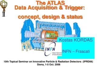
Trigger DAQ Calo MuTrCh Other detectors ~ 1 PB/s 40 MHz 40 MHz LVL1 2.5 ms LVL1 accept Calorimeter Trigger Muon Trigger ROD ROD ROD Read-Out Drivers 75 kHz RoI’s 120 GB/s Read-Out Links RoI requests LVL2 ROB ROB ROB ~ 10 ms ROS Read-Out Buffers ROIB L2SV Read-Out Sub-systems RoI data = 1-2% ~2 GB/s L2P L2P L2P ~2 kHz ~3 GB/s L2N LVL2 accept Event Builder Event Filter ~ 1 sec EB ~3 GB/s EFN EFP EFP EFP ~ 300 MB/s ~ 200 Hz ~ 300 MB/s ARCHITECTURE FE Pipelines 2.5 ms H L T ATLAS TriggerDAQ
The Trigger Framework • The development and testing of event selection code used the off-line software framework (Athena) • The event selection code was then ported to the on-line “DataCollection” framework • Latter provides the interfaces to the on-line services (e.g. run control, configuration, message passing). • But an increasing number of services provided in off-line code would need to be ported and maintained for on-line use • Including services required to handle calibration and alignment data • The TDR introduced the “PESA Steering Controller” (PSC) to reduce this on-going effort ATLAS TriggerDAQ
The Trigger Framework • The PSC is an interface inside the on-line application • Provides “Athena-like”environment (i.e. off-line) • Hides the on-line complications from the event selection s/w ATLAS TriggerDAQ
The Trigger Framework • The PSC allowed the use of many off-line services • Simplifies trigger code development and testing • Provides direct access to s/w to handle calibration/alignment • Greater homogeneity between off-line and on-line code • Event selection code in L2 and EF see the same environment – so eased moving algorithms between them • In principle still allowed multiple algorithm threads in a single application – in practice proved no longer practical • e.g. some offline services used external libraries which were not thread-safe • Hence L2 moved to use of many off-line services – but dropped multiple algorithm threads • Still need thorough testing of services introduced • to ensure that they met the online requirements (timing, memory leaks and robustness) ATLAS TriggerDAQ
Event Selection Code • HLT algorithms: • Extract features from sub-detector data • Combine features to reconstruct physical objects • electron, muon, jet, etc • Combine objects to test event topology • Organised into Trigger Chains • Trigger Chain: • Started if seed has fired • Processing of a chain stops as soon as an algorithm not passed • Chain passes if last Hypothesis in the chain is passed • Can be used to seed other chains in next level • Trigger Menu • Consists of a list of triggers including prescales at each level • i.e. L1 Item -> L2 Chain -> EF Chain • Can enable/disable a trigger during a run using the prescales • Event passed if at least one EF Chain passed ATLAS TriggerDAQ
EM ROI Execution of a Trigger Chain L2 calorim. Level1: Region of Interest is found and position in EM calorimeter is passed to Level 2 Electromagnetic clusters cluster? L2 tracking track? • Level 2 seeded by Level 1 • Fast reconstruction algorithms • Reconstruction within RoI match? E.F.calorim. E.F.tracking track? • Ev.Filter seeded by Level 2 • Offline reconstruction algorithms • Refined alignment and calibration e/ reconst. e/ OK? ATLAS TriggerDAQ
Changes since the TDR • Multi-core technology – the 8GHz (and faster) CPU clocks did not appear, have to use multi-cores. Major impact to date is how to handle the large increase in number of applications! • XPU racks – the initial HLT racks are connected to both DataCollection network (for L2) and Back-End network (for EF) • Fewer but larger more performant SFOs • Concept of Luminosity blocks – defines a short period (1-2 mins) where running is stable – implemented using a Tag added in L1-CTP • Allows parts of the system to be removed/added within a run • Allows a synchronised change of Trigger Pre-scales within a run • Event streaming – separate files for different event types (express, different physics streams, calibration, debug etc) • Partial Event Building added – for greater flexibility in calibrations • Better scaling by more proxies (e.g. for Databases, Information Servers, gathering of histograms) • Better monitoring and configuration tools ATLAS TriggerDAQ
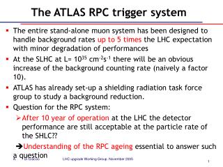
ATLAS TDAQ System CERN computer center [~5 ] [~1600] [~100] [~ 500] [26] Local Storage SubFarm Outputs (SFOs) Event Filter (EF) farm Event Builder SubFarm Inputs (SFIs) Level 2 farm Control+ Configuration Data Storage [48] [1] Monitoring SDX1 DataFlow Manager Network Switches [70] [4] File Servers Level 2 Super- visors surface Event data requests & Delete commands underground USA15 Requested event data ATLAS Data VME bus [~ 150] UX15 ~1600 Read-Out Links Read- Out Drivers (RODs) Read-Out Subsystems (ROSes) Trigger Info [# nodes] ROI Builder Level 1 trigger Control, Configuration and Monitoring Network not shown Region Of Interest (ROI) ~90M channels ~98% fully operational in 2010 Timing Trigger Control (TTC) ATLAS TriggerDAQ
Other Components/Issues • No time to include many other important aspects • In particular: • Run Control • Monitoring - of the infrastructure and of the data • Configuration - of the many O(10K) applications • Error reporting • Use of databases • Calibration runs • Scaling of all of the above ATLAS TriggerDAQ
Status in 2010 Running ATLAS TriggerDAQ
TDAQ Farm Status • 27 xpu racks ~800 xpu nodes • XPU = L2 or EF Processing Unit can be configured to run either as L2 or EF on a “run by run” basis • Possibility to move processing power between the L2 and the EF allows high flexibility to meet the trigger needs ATLAS TriggerDAQ
DataFlow rates Achieved Output from ROS • Have exceeded by a good margin the TDR specification of 20 kHz L2 data requests together with EB requests of 3 kHz Event Building • Have sustained data rates of well over 4.5 GB/s for a wide range of event sizes (100kB to 10MB) • An EB test with 1.3 MB events achieved 9 GB/s SFO Output • Have sustained running at well over 1 GB/s • cf 300 MB/s in TDR • Output to Computer Centre runs at up to ~900 MB/s ATLAS TriggerDAQ
ATLAS Run Efficiency • ATLAS Efficiency @Stable Beams at √s = 7 TeV • (not luminosity weighted) • Run Efficiency 96.5% (green): fraction of time in which ATLAS is recording data, while LHC is delivering stable beams • Run Efficiency Ready 93% (grey): fraction of time in which ATLAS is recording physics data with innermost detectors at nominal voltages (safety aspect) • Key functionality for maximizing efficiency • Data taking starts at the beginning of the LHC fill • Stop-less removal/recovery: automated removal/ recovery of channels which stopped the trigger • Dynamic resynchronization: automated procedure to resynchronize channels which lost synchronization with LHC clock, w/o stopping the trigger 752.7 h of stable beams (March, 30th - Oct, 11th) ATLAS TriggerDAQ
Trigger Menu and Configuration Trigger menu: • Collection of trigger signatures • ≈200 – 500 algorithm chains in current menus • Algorithms re-used in many chains • Selections dictated by ATLAS physics programme • Includes calibration & monitoring chains Configuration infrastructure • Very flexible! • Pre-scale factors employed to change menu while running • At change of Lumi Block • Adapt to changing LHC luminosity ATLAS TriggerDAQ
Trigger Commissioning • Initial timing in of L1 with Cosmics +single beams : • First Collisions : L1 only • Since June : gradual activation of HLT ATLAS TriggerDAQ
Beam spot monitoring in L2 • Example of using the flexibility and spare capacity in the system • Fit Primary vertex using tracks to Inner Detector data • Does not use RoI, so limited to a few kHz – because of ROS request limit • Very useful diagnostic during 2010 for LHC tuning ATLAS TriggerDAQ
Evolution of LHC Luminosity in 2010 ATLAS TriggerDAQ
Total Integrated Luminosity in 2010 ATLAS TriggerDAQ
Summary of 2010 p-p running • The ATLAS TDAQ system has operated beyond design requirements • meeting changing needs for trigger commissioning, understanding the detector and accelerator, and delivering physics results • Robust and Flexible system • thanks to years of planning, prototyping, commissioning and dedicated work by many people • The data Recording farm regularly used well beyond design specifications • The system (dataflow and trigger) has successfully handled running with luminosity spanning 5 orders of magnitude • There is space for the trigger to evolve and the selections will continue to be optimized for even higher luminosities • There are enough HLT nodes to meet the full EB rate and present L • If needed will install more CPU power in 2011 • High Run Efficiency for Physics of 93% • Ready for running in 2011 ATLAS TriggerDAQ
Moved on to 4 weeks of Heavy Ion running ATLAS TriggerDAQ