Download
1 / 62
620 likes | 730 Views
LHC. From LCLS to LHC: Light from Electrons, Protons, and even Lead Ions. Alan Fisher ARD Status Meeting 2011 January 6. Terahertz Radiation from LCLS Electrons. Electrons passing through a metal foil emit intense, coherent transition radiation (CTR) at wavelengths l bunch length.

E N D
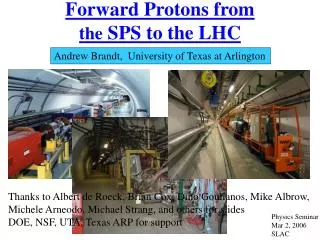
LHC From LCLS to LHC:Light from Electrons, Protons,and even Lead Ions Alan Fisher ARD Status Meeting 2011 January 6
Terahertz Radiation from LCLS Electrons • Electrons passing through a metal foil emit intense, coherent transition radiation (CTR) at wavelengths l bunch length. • Highly compressed LCLS bunches: l 10 to 100 µm • Corresponding frequencies: 3 to 30 THz • Intense pulses with the time structure of the electron beam • Powerful diagnostic tool for the beam’s temporal profile • When focused: • Electric fields > 1 GV/m = 0.1 V/Å (depends on bunch charge, length) • Magnetic fields > 3 T • Well above other THz sources • Duration of tens of fs • Powerful enough to pump femtosecond chemistry and nonlinear behavior in materials
Terahertz Collaborators • LCLS • Henrik Loos • Stefan Moeller • Jim Turner • Gene Kraft • Dave Rich • Rob McKinney • Roenna del Rosario • Frank Hoeflich • John Wagner • PULSE • Aaron Lindenberg • Dan Daranciang • John Goodfellow • Shambhu Ghimire • FACET • Ziran Wu • University of Maryland • Ralph Fiorito • Anatoly Shkvarunets
Calculated Field and Spectrum Electric Field Spectrum At the THz focus, for a 1-nC, 20-fs bunch Calculations by Henrik Loos
Terahertz Layout • Extract THz in the Undulator Hall • Pneumatic actuator, 30 m past the end of the undulator, inserts a thin beryllium foil at 45° to the electron beam • Electrons and hard x-rays pass through • THz light goes downward through a diamond window to an optical table below • Measurements • Joulemeter: Energy • Pyroelectric video camera: Size at focus • Michelson interferometer: Spectrum • Will soon install a 20-fs Ti:sapphire laser on the table • Electro-optic measurements of electron bunch • THz/laser pump/probe studies of materials • Proof of principle for a future THz/x-ray pump/probe upgrade • Requires a long THz transport line to the NEH
Beryllium Foil • Thickness: 2 µm • Diameter: 25 mm • Electrons go through with little scattering or radiation • Transparent to hard x rays • Can be used parasitically • Absorbs x rays below 2 keV • For soft x-ray experiments, foil must be pulled out 2-µm Be Foil at 45° X-Ray Transmission Photon Energy [eV]
Beamline and Optical Table Beryllium foil Pneumatic actuator Diamond window Track for laser curtain e− Laser chiller Control rack
Foil in 6-way Cross Pneumatic actuator Beryllium foil Bellows Diamond window
Optics for First Measurements Initial Characterization of the Terahertz Radiation: Energy and Profile at Focus 2010 October 12 Filter wheel Fluorescent card Pyrocam Off-axis parabolic mirror Translation stage: Move through focus Joulemeter HeNe Si Fluorescent card Fluorescent card (flip up) (Enclosure 1) Elevation View Plan View
Complete Optics Layout Optics enclosure The optics will be enclosed for laser safety and for a dry-air purge.(Water has THz absorption lines.)
THz Energy versus Charge and Bunch Length • Electric field E of a relativistic bunch varies with bunch charge q and duration t : E ~ q/t • Energy in the pulse then follows: E2t ~ q2/t • Compare a q2/t fit (open circles) to the measured THz (solid) for two bunch-charge values
Transmission of GaAs versus THz Intensity • Translate a GaAs wafer through the THz focus (at z = 0) • Transmitted THz energy shows nonlinear absorption
Michelson Interferometer: THz Spectrum • Scan of Michelson delay gives an autocorrelation • Fourier transform of autocorrelation yields the power spectrum • Still being commissioned, but we have preliminary data Pyroelectric detector Delay scan Si beamsplitter Fourier transform I(ω) I(t) Delay stage
Insight from Simulations 350 pC, 50 fs 1 nC, 20 fs 1 nC, 60 fs 350 pC, 115 fs
Summary of Spectral Findings • Short bunches show a broad spectrum peaking at 10 THz, consistent with a single-cycle pulse. • Long bunches have nodes in the spectrum, corresponding to ripples in the time domain from imperfect compression. • The width of the autocorrelation trace is consistently shorter than the value from the electron bunch-length monitor • Better electronics are on order to greatly speed up the scans. • A laser synchronized with the beam will be installed in February, allowing THz pump/optical probe experiments and direct measurements of time-dependent E-field.
Transport to the NEH • A 100-m transport line is needed to relay the THz light from the source to an NEH hutch. • Sequence of off-axis parabolic (OAP) mirrors, to alternate between collimation and focusing to a waist • Diffraction demands large mirrors and frequent refocusing • For example, 400-mm-diameter mirrors with a focal length of 5 m, spaced every 10 m • 90° bend at each OAP lengthens the path • THz arrives tens of nanoseconds after the x rays • We want THz/x-ray pump/probe, but this gives probe/pump!
Two Electron Bunches • To get the THz radiation to a user before the x rays arrive, we’ll need two electron bunches, separated by tens of ns • First bunch has a high charge, optimized for THz • That would lase poorly in the FEL, but we can also spoil the gain: • Turn up the laser heater: Excessive energy spread • Or add a fast kicker: Orbit oscillation along the undulator • Choose an RF bucket for first pulse so that it arrives ps before x rays • THz “optical trombone” delay line then tweaks the arrival time • Second bunch makes x rays • A second THz pulse arrives tens of ns after pump/probe • No problem for users because it is so late • If necessary, a fast kicker could force electrons to miss the foil • Test in July: 2 equal bunches, 8.4 ns apart • Both bunches were lasing in the FEL
2010-07-28: Two-Bunch Test in LCLS • 2 bunches, 8.4 ns apart • Photodiode viewing 2 x-ray pulses on YAG screen • 10 ns/div • Both pulses, adjusted to have slightly different energies, on the SXR spectrometer • Upgrade of instrumentation (BPMs, toroids) required to measure individual bunches
Synchrotron-Light Monitors for the LHC • Five applications: • BSRT: Imaging telescope, for transverse beam profiles • BSRA: Abort-gap monitor, to verify that the gap is empty • When the kicker fires, particles in the gap get a partial kick and might cause a quench. • Abort-gap cleaning • Longitudinal density monitor (in development) • Halo monitor (future upgrade) • Two particle types: • Protons • Lead ions (1 month a year): First ion run was in November/December • Three light sources: • Undulator radiation at injection (0.45 to 1.2 TeV protons) • Dipole edge radiation at intermediate energy (1.2 to 3 TeV) • Central dipole radiation at collision energy (3 to 7 TeV) • Consequently, the spectrum and focus change during the energy ramp
CERN Collaborators • Stéphane Bart-Pedersen • Andrea Boccardi • Enrico Bravin • Stéphane Burger • Gérard Burtin • Ana Guerrero • Wolfgang Hofle • Adam Jeff • Thibaut Lefevre • Malika Meddahi • Aurélie Rabiller • Federico Roncarolo My work at CERN has been supported by SLAC through the DOE’s LHC Accelerator Research Program (LARP).
Power Radiated by a Charge in a Dipole • A relativistic charge q = Ze with mass m, velocity bc c, and energy E = eEeV = gmc2 travels through a dipole field Bd • Radius of curvature of the orbit: • Lead ions: Since r and Bd don’t change, the maximum energy must be Z = 82 times higher—574 TeV, or 100 J per ion! • Equal to the kinetic energy of 82 mosquitos flying at 1 m/s • Or, a 1-mm grain of sand thrown at 40 km/h • Power emitted in synchrotron radiation: • The factor of g 4 makes the radiated power substantial—except in the LHC, where the protons have a g of 7500, but r = 6 km. • The factor of Z2g 4 means that ions radiate more than protons by a factor of 826/2084 = 162
Spectrum and Critical Frequency Critical Wavelength vs. LHC Beam Energy Spectrum near Critical Frequency Lead ions Protons Camera response • Normalized dipole emission, intergrated over vertical angle y, versus energy E/Ec • Long tail for E < Ec • Visible light << Ec for electron rings • Rapid drop in emission for E > 10Ec • Peak is below Ec • Cameras respond from near IR to near UV • Proton emission wavelengths are too long to see below ~1.2 TeV • Ion emission is too long below ~3 TeV • Ion energy given as “equivalent proton energy”: Dipole set to the same field as for 3-TeV protons
Superconducting Dipole + Undulator • Add an undulator inside the dipole’s cryostat • Dipole: • Field for 7 TeV 3.88 T • Length 9.45 m • Radius of bend 6013 m • Bend angle 1.57 mrad • Undulator: • Peak field 5 T • Periods 2 • Period length 280 mm • Pole gap 60 mm • Wavelength for 609 nm450-GeVprotons (injection) Undulator layout and field map Undulator inside cryostat
Undulator Emission versus Beam Energy • Undulator peak is red for injected protons, but moves into the ultraviolet at 1 TeV. Dipole light is still in the infrared. • Injected ions can be seen only with the weak high-energy tail. • Radiation from a 2-period undulator has a broad bandwidth. Camera response Lead ions Protons
Short Dipoles and Edge Radiation • Radiation from the dipole’s edge fills the gap during the energy ramp between the undulator and the central dipole light. • If the dipole is short, the observer sees a faster “blip” of radiation, which pushes the spectrum to higher frequencies. • Rapidly rising edge field of a (long) dipole has the same effect. Fisher — Imaging with Synchrotron Light
Photoelectrons per Particle at the Camera Protons Lead Ions Dipole center Combined Dipole center Combined Dipole edge Dipole edge Undulator Undulator • In the crossover region between undulator and dipole radiation: • Weak signal • Two comparable sources: poor focus over a narrow energy range • Focus changes with energy: from undulator, to dipole edge, to dipole center • Dipole edge radiation is distinct from central radiation only for w >> wc
Layout: Dipole and Undulator Cryostat 70 m 194 mm To RF cavities and IP4 To arc 1.6 mrad 420 mm D4 10 m D3 U Extracted light sent to an optical table below the beamline 560 mm 26 m 937 mm
BSRT for Beam 1 Door toRF cavities Undulator and dipole Beam 1 Beam 2 B1 Extraction mirror(covered to hunt for a light leak) Optical Table
Table Enclosure under Extraction Mirror Beam 1 Beam 2 B1 Extraction mirror
Extraction Mirror Protons—with their small heat load—can use a simple mirror without cooling.
Layout of the Optics Extraction mirror Beam Optical Table Shielding Alignment laser Calibration light and target PMT and 15% splitter for abort gap monitor F1 = 4 m F2 = 0.75 m Cameras Intermediate image Focustrombone Slit Table Coordinates [mm]
LHC Beams at Injection (450 GeV) Beam 1 Beam 2 Horizontal 1.3 mm 1.2 mm Vertical 0.9 mm 1.7 mm Light from undulator. No filters.
Beam 1 at 1.18 TeV • 1.18 TeV has the weakest emission in the camera’s band. • Undulator’s peak has moved from red to the ultraviolet • Dipole’s critical energy is still in the infrared • Nevertheless, there is enough light for an adequate image. • Some blurring from two comparable sources at different distances • Vertical emittance growth before and after ramp • Comparing synchrotron light to wire scanner Vertical Emittance Synchrotron Light Wire Scanner Proton Energy
LHC Beams at 3.5 TeV Beam 1 Beam 2 Horizontal 0.68 mm 0.70 mm Vertical 0.56 mm 1.05 mm Light from D3 dipole. Blue filter.
First Lead-Ion Images, 2.3 TeV First ramp of one bunch of lead ions 2011 November 5
Calibration Techniques 5 mm • Target • Incoherently illuminated target (and alignment laser) on the optical table • Folded calibration path on table matches optical path of entering light • Wire scanners • Compare with size from synchrotron light, after adjusting for different bx,y • Only possible with a small ring current • Beam bump • Compare bump of image centroid with shift seen by BPMs
Emittance Comparisons at 450 GeV Beam 1 Horizontal Beam 1 Vertical LHC Synchrotron Light LHC Wire Scanner Nominal e From SPS Beam 2 Horizontal Beam 2 Vertical Time [h] Time [h]
Disagreement with Wire Scanners • The horizontal size—but not the vertical—measured with synchrotron light is larger than the size from the wire scanners. • Beam 1: Factor of 2 in x emittance (2 in beam size) • Beam 2: Factor of 1.3 in x emittance • b beat isn’t large enough to explain this. • I tested the full system in the lab in 2009 • Found distortions on the first focusing mirrors (old, perhaps left-overs from LEP?) • Replacements arrived just before tunnel was locked: No time for tests
Nov 2010: Bench Tests with Duplicate Optics • I set up a new 4.8-m 0.8-m table in the lab with a copy of the tunnel optics. • Alignment of tunnel optics: • Images shift while focusing: mirrors not properly filled • More diffractive blurring? • New alignment procedure • Entering light needs one more motorized mirror • Camera and digitizer: • Fixed hexagonal pattern from intensified camera • Increased magnification reduces the effect • Digitizer grabs every other line 500-µm line width 400-µm line width
BSRA: Abort-Gap Monitor • Gated photomultiplier receives ~15% of collected light • PMT is gated off except during the 3-ms abort gap: • High gain needed during gap • Avoid saturation when full buckets pass by • Beamsplitter is before all slits or filters, to get maximum light • Gap signal is digitized in 30 100-ns bins • Summed over 100 ms and 1 s • Requirement: Every 100 ms, detect whether any bin has a population over 10% of the quench threshold • Integration over 1 s is needed where PMT signal is weak • Protons near 1.2 TeV • Worst case signal-to-noise is 10 for 1-s integration with a population of 10% of quench threshold • No PMT signal observed for an ion bunch at injection energy • Calculations said there should be a signal • Does PMT not extend into the near IR as far as the datasheet claims?
Protons/100ns at the Quench Threshold Protons in a pilot bunch Original specification Model for BSRA (Q4 quench) (M. Sapinski) General quench model (B. Dehning) • Original thresholds, specified only for 0.45 and 7 TeV, were too generous • Must detect levels well below a pilot bunch • BLM group provided improved models: using Sapinski’scalculation • Ion threshold is scaled from proton threshold: • Ion fragments on beam screen • Deposits same energy as Z protons at same point in ramp
Calibration of BSRA • Inject a pilot bunch • Charge measured by bunch-charge and DC-current electronics • Attenuate light by a factor of bunch charge / quench threshold • Move BSRA gate to include the pilot bunch • Find PMT counts per proton (adjusted for attenuation) as a function of PMT voltage and beam energy • Turn RF off (coast) for 5 minutes to observe a small, nearly uniform fill of the gap • Useful to test gap cleaning… Last bunch in fill First bunch in fill Pilot bunch Abort gap After coasting briefly, bunch spreads out Time [100-ns bins]
2009 Dec 16: Test of Abort-Gap Cleaning • Injected 4 bunches into Beam 2 • Poor lifetime, but not important for this experiment • Turned off RF, and coasted for 5 minutes • Abort-gap monitor detected charge drifting into the abort gap • Excited 1 µs of the 3-µs gap at a transverse tune for 5 minutes • How well did this work? Look inside the gap... RF off Beam dumped Gap cleaning RF on(poor lifetime) Beam charge (injection) Total PMT signal(negative going) in all 30 bins 0 25 minutes
Charge in Abort Gap Abort gap (3 µs) Beam dumped Excitation had ringing on the trailing edge (improved in January) Time (s) Cleaning started in 1-µs region: Immediate effect Charge drifting from first bunch after gap RF off: coasting beam Position in fill pattern (100-ns bins)