Download
1 / 22
220 likes | 332 Views
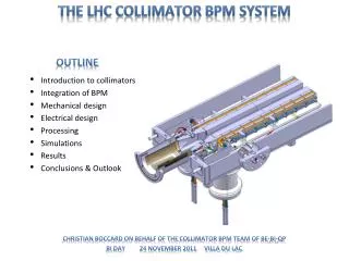
Collimator BPM electronics – Results from the lab, SPS and LHC Marek Gasior BE-BI-QP. Outline: The principle of the novel Diode ORbit (DOR) measurement system Lab measurements SPS measurements LHC measurements. WHY diode detectors ?.

E N D
Collimator BPM electronics – Results from the lab, SPS and LHC Marek Gasior BE-BI-QP • Outline: • The principle of the novel Diode ORbit (DOR) measurement system • Lab measurements • SPS measurements • LHC measurements
WHY diode detectors ? • Diode detectors can be used to convert fast beam pulses (LHC bunch length is in the order of 1 ns) from a BPM into slowly varying signals, possible to digitise with high resolution. • As the diode forward voltage Vd depends on the diode current and temperature, the output voltage of a simple diode detector also depends on these factors. • Simple diode detectors are no good for precise amplitude measurement. Input (Vi) and output (Vo) voltages of a peak detector with an ideal diode Input (Vi) and output (Vo) voltages of a peak detector with a real diode Input (Vi) and output (Vo) voltages of an average-value detector Collimator BPM electronics: Diode Orbit System
Compensated diode detector • Compensated diode detector consists of two diode peak detectors, one with single, second – with two diodes. All three diodes are in one package, for good thermal coupling and symmetry of the forward voltages Vd. • Two operational amplifiers are used to derive 2Vd voltage and to add it to the output of the two-diode detector. This way the resulting output voltage is equal to the input peak voltage. • To get an “ultimate peak mode operation”, the discharge resistors can be omitted. In this case the discharge is done by the reverse leakage current of the diodes. • The asymmetry in the charging conditions becomes less important for larger input voltages. Collimator BPM electronics: Diode Orbit System
Diode ORbitFront-End • Signal of each pick-up electrode is processed separately. • The multiplexer is foreseen for calibration with beam signals. • The low pass filters decrease the signal amplitude and make the beam pulses longer. • The conversion of the fast beam pulses into slowly varying signals is done by compensated diode detectors. • These slow signals can be digitised with high resolution, averaged and transmitted at slow rates. • All further processing and calculations are done in the digital domain. • ADC data sent as UDP packets. • Sample averaging is the only data processing done by the microcontroller.Sampling is at 11.7 kHz. Typical averaging is down to 1 Hz. • UDP data is received by the host computer, calculating the position, making logging, etc. • Simple and robust hardware, high resolution, no beam synchronous timing required. Collimator BPM electronics: Diode Orbit System
DOR FE is still a prototype Collimator BPM electronics: Diode Orbit System
DOR FE connected to two LHC BPMs Collimator BPM electronics: Diode Orbit System
DOR prototype: lab measurements • Inputs of all 4 FE channels parallel, simulating beam in the PU centre. • Input signal: 10 MHz sine wave, FE gain 25 dB (max). • Raw results, without any offset and gain calibration. • 24-bit 8-channel ADC sampling at 11.7 kHz, samples averaged in the microcontroller to 50 Hz equivalent sampling, then to 1 Hz for the plots. • Front-end channels have 10 Hz LP filters before the ADCs. • Amplitude changes due to temperature sensitivity of the signal generator. • The amplitude faster jumps may be due to some internal calibration of the generator or somebody (i.e. me) touching the input cables, as during the night signals were much smother. Collimator BPM electronics: Diode Orbit System
DOR prototype: lab measurements The plot repeated from the previous slide • Beam position calculated as for an LHC arc pick-upwith 49 mm electrode distance. • 49 mm of a regular BPM is equivalent to the collimator BPM gap of about 29 mm (as each BPM button is 10 mm below the jaw surface). • ”Natural” long term stability shown, no calibration. Collimator BPM electronics: Diode Orbit System
DOR prototype: lab measurements • All 4 inputs in parallel, simulating beam in the PU centre and changing beam intensity. • Input: 10 MHZ sine wave with slow triangular modulation to simulate intensity changes, FE gain 25 dB (max). • Raw results, without any offset and gain calibration. • Beam position calculated as for an LHC arc pick-up with 49 mm electrode distance (coll. BPM gap of 29 mm). • ADC sampling at 11.7 kHz, samples averaged to 50 Hz equivalent sampling. • Front-end channels have 10 Hz LP filters before the ADCs. Collimator BPM electronics: Diode Orbit System
DOR prototype: lab measurements • Now channels 2, 3, 4 are correlated with channel 1, resulting in the coefficients (offset, gain), in the ADC full scale (FS) units:ch2: -0.001720, 1.002262ch3: 0.000325, 0.998747ch4: -0.001247, 1.000359 • Channel difference improved from 103 to 105 level, by some 2 orders of magnitude. • Position error improved also by some 2 orders of magnitude. • For amplitudes larger than 20 % of the full scale the noise is not larger than some 50 nm peak-peak, i.e. some 10 nm rms. This is with the 25 dB gain of the high-frequency input amplifiers, 50 Hz ADC equivalent sampling and 10 Hz analogue bandwidth for the orbit changes. • The final diode front-end will be equipped with a calibration circuitry capable of connecting the same signal of programmable amplitude to all inputs. • The input circuitry will allow the same with beam signals, i.e. the same beam signal can be connected to both front-end channels processing one pick-up plane. Collimator BPM electronics: Diode Orbit System
DOR prototype: lab measurements • Input signal made different with fixed attenuators, simulating an offset beam + beam intensity changing. • Simulated beam offset is the same for both pick-up planes (both planes connected in parallel). • Input signals, gain and sampling as before for the simulated centred beam. • Errors some 2 orders of magnitude larger than for the centred beam. • Correlating channels does not help significantly. • Position measurement dependency on signal intensity for large beam offsets will be addressed in the future development. 100 µm Collimator BPM electronics: Diode Orbit System
DOR prototype: lab measurements with a calibration mux • Measurement with 4 equal signals and calibration mux (not switching), results scaled to 49 mm aperture (i.e. equivalent to 29 mm gap of the collimator BPM). • Correlation coefficients used to calibrate the channels, the same coefficients for the whole measurement. Collimator BPM electronics: Diode Orbit System
DOR on collimator BPM: Measurements with the SPS beam • Main role of the embedded BPM system is to indicate when the beam is in the middle between the jaws, i.e. when the signals from the opposing electrodes are equal. • Geometrical factor, a constant for “static” BPMs, changes with the jaw distance, fortunately not dramatically, up to some 30 %. • Signal amplitude changes with the jaw distance by a factor of 3. • Very interesting case from academic point of view (lab-type measurement possible with real beam, online calibration by BPM precise movement). • Measurements with one LHC nominal bunch LU right upstream button left upstream button right downstream button left downstream button LD RU RD Drawing from A.Nosych Collimator BPM electronics: Diode Orbit System
DOR on collimator BPM: beam tests on the SPS Collimator BPM electronics: Diode Orbit System
LHC: standard vs. DOR processing comparison • BPM electrode signals are split and send to both systems • Beam position calculation using the same polynomial • Aperture 61 mm Collimator BPM electronics: Diode Orbit System
LHC: standard vs. DOR processing comparison Collimator BPM electronics: Diode Orbit System
LHC: standard vs. DOR processing comparison Collimator BPM electronics: Diode Orbit System
Conclusions • A new technique was developed to process collimator BPM signals with very high resolution. • It is optimised for: • position resolution; • absolute accuracy of beam centring; • robustness and simplicity. • It assumes: • bunch-by-bunch is not needed; • required bandwidth is in the Hz range; • Larger beam offsets (> 1 mm) do not have to be measured with high precision (< 1 µm). • Demonstrated sub-micrometre resolution with single SPS bunches and large collimator gaps. • Potentially interesting for precise orbit measurements in critical LHC locations. • Things to work on: • linearity of the compensated diode detectors; • system integration. BPM Signal Processing with Diode Detectors
Spare slides Collimator BPM electronics: Diode Orbit System
Simple diode detectors for BPM signals • One diode detector for each BPM electrode. • Subtracting signals before the detectors (e.g. by a 180° hybrid) is no good, as the resulting signals would be: • smaller (→ larger nonlinearities); • changing signs when crossing the BPM centre. • The diode forward voltage Vd introduces a significant position error. • Vd depends on the diode current and temperature. • Simple diode detectors are good for applications when the signal amplitude is not that important. • Two examples: • Tune measurement systems • An LHC safety system: Beam Presence Flag BPM Signal Processing with Diode Detectors
DOR prototype: lab measurements with a calibration mux Collimator BPM electronics: Diode Orbit System
DOR prototype: lab measurements with a calibration mux corr. for 1 s every 1 h correlation for 60 s corr. for the whole meas. as above, projected to a 49 mm aperture whole Collimator BPM electronics: Diode Orbit System