Download
1 / 18
180 likes | 307 Views
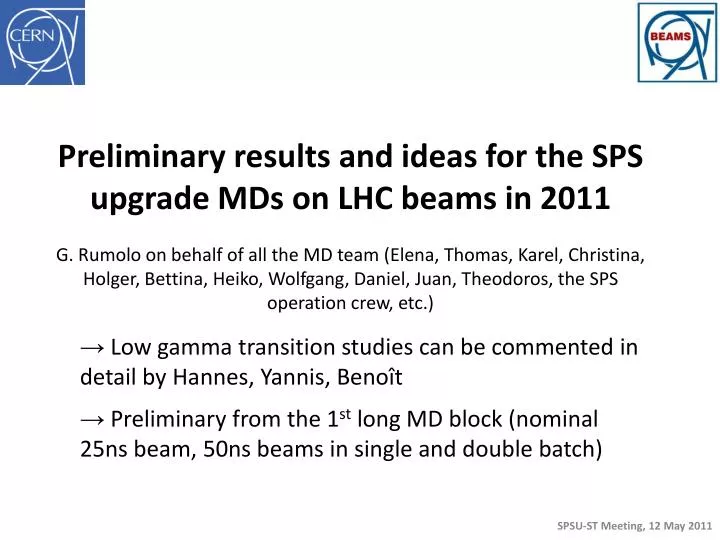
Preliminary results and ideas for the SPS upgrade MDs on LHC beams in 2011 G . Rumolo on behalf of all the MD team (Elena, Thomas, Karel , Christina, Holger , Bettina, Heiko , Wolfgang, Daniel, Juan, Theodoros , the SPS operation crew, etc.).

E N D
Preliminary results and ideas for the SPS upgrade MDs on LHC beams in 2011 G. Rumolo on behalf of all the MD team (Elena, Thomas, Karel, Christina, Holger, Bettina, Heiko, Wolfgang, Daniel, Juan, Theodoros, the SPS operation crew, etc.) • Low gamma transition studies can be commented in detail by Hannes, Yannis, Benoît • Preliminary from the 1st long MD block (nominal 25ns beam, 50ns beams in single and double batch)
We started parallel MDs in week 17 • Preparation for the LHC MDs (week 18) and long injector MD block (week 19) • Longitudinal emittance blow up • Instabilities at flat top related to radial steering • Low gamma transition • Long MD block in Week 19 split around the technical stop
Low gamma transition studies (Q20) were planned to start with single bunch on a parallel MD1 cycle (no acceleration) or LHCFAST (fast ramp to 450 GeV/c) • However, in order not to have to optimize twice the set up of this beam along the ramp, it was decided to use a 1-inj cycle with slow ramp, instead of the LHCFAST (9bp instead of the 6bp of the fast ramping cycle)
So far, single bunches studies done on Q20 with intensities up to 3 x10¹¹ and very low transverse emittances (~1 mm in both transverse planes) • The idea was to • do the set up and study transmission on the short cycle • explore beam behavior (i.e. loss and emittance growth) on a long flat bottom and over the long cycle as a function of the injected intensities and emittances
Long MD block in Week 19 (Monday): • Monday daytime: Set up of the 25ns beam (longitudinal parameters, transverse feedback system) • Monday night: supercycle composed of two concurrent long flat bottom cycles, one for the 25ns beam and the other one for Q20 with single bunch Injection and acceleration of 4 batches with losses down to 3-4% Injection and acceleration of single bunch of up to 3 x 10¹¹ protons: small loss on the flat bottom and capture loss
MD with 25ns beam (1): • Nominal intensity • Up to 4 batches injected • Very low losses along the cycle (reproducible 3-4%)
MD with 25ns beam (2): • Nominal intensity • Emittances measured in the PSB and the PS • PSB Eh=2.9 mm, Ev=2.0 mm averaged over the 4 rings (further optimization could be done) • PS (different from different WSs, ignored FWS54H and averaged readings from the others): Eh=2.9 mm, Ev= 1.5 mm • Emittances consistently measured in the SPS at every injection step • Remarkably low emittances measured at flat top in the SPS: • Eh=2.4 mm • Ev=2.7 mm
MD with 25ns beam (3): • Electron cloud measured at all the liners • Signal already visible with 1 batch on both stainless liners • No signal visible on the a-C coating liner • Half signal clearly visible on the half coated chamber • Effect of the clearing electrode checked scanning points on a grid of voltage vs. magnetic field values Clearing electrode: it was switched off in the middle of cycle Half-coated liner, only stripe on StSt visible
MD with 25ns beam (4): • Problems: • ZS had two vacuum spikes, even with the voltage applied, as from last year • MKE heating: MKE4 (Tank 5) reached 70oCand interlocked the beam (4 minutes stop, then Q20 re-started, while we waited longer for the 25ns beam, which we anyway stopped accelerating)
Long MD block in Week 19 (Wednesday): • Wednesday daytime: • MD started as scheduled at 8:00am thanks to Karel & operation crew, who did the re-alignment after the quadrupole exchange during the night! • 50ns double batch (1.4x 10¹¹ ppb at flat top) in the first part • 50ns double batch (close to 1.7 x 10¹¹ ppb at flat top) in the second part Injection and acceleration of single bunch of up to 3 x 10¹¹ protons: small loss on the flat bottom and capture loss Injection and acceleration of 4 batches with losses less than 3%
Long MD block in Week 19 (Wednesday): • Wednesday night: • The switch to the 50ns single batch happened during the night due to a ~5h stop of the MD in the afternoon, caused by a Linac intervention (urgent replacement of a sparking RF modulator) • 50ns single batch (1.2x 10¹¹ ppb at flat top, nominal) in the first part • 50ns single batch (close to 1.45 x 10¹¹ ppb at flat top) in the second part Injection and acceleration of single bunch of up to 3 x 10¹¹ protons: small loss on the flat bottom and capture loss Injection and acceleration of 4 batches with losses less than 3%, later optimized to less than 2%
MD with 50ns double batch beam (1): • Intensity higher than nominal (we were initially deceived by the fastBCT, which is not correctly calibrated for 50ns beams) • Up to 4 batches injected • Very low losses along the cycle (reproducible 3%)
MD with 50ns double batch beam (2): • 1.4 x 10¹¹ ppb at flat top • Emittances consistently measured in the SPS at every injection step • Emittances always measured both at injection (after the last injection) and at flat top in the SPS and no emittance growth observable • Emittances at flat top, clean beam shape: • Eh=1.7 mm • Ev=1.7 mm
MD with 50ns double batch beam (3): • Electron cloud measured at all the liners • Signal already visible with 1 batch only on the stainless liner without clearing electrode! • No signal visible on the a-C coating liner • No signal visible on the half coated chamber (was in since last year) • The two StSt liners were installed at same time (January 2011), why did we scrub more the one with the clearing electrode? • More efficient scrubbing from high energy electrons/ions? • Baking from beam induced heating?? StSt not yet scrubbed below 1.7 (expected threshold for 50ns beams) Scrubbed StSt with clearing electrode Great job from the VSC team that exchanged the quadrupole in LSS5 during TS, as no surface degradation is visible!!!!
MD with 50ns double batch beam (4): • Very close to ultimate intensity 1.65 x 10¹¹ ppb at flat top • Heiko in the PS used the 3 x 80 MHz cavities to increase/decrease the longitudinal blow up before injection into the SPS • Found an intermediate configuration, which would not worsen capture losses and also keep the beam stable in the SPS, since the longitudinal blow up in the SPS with band-limited noise could not be optimized quickly (subject of one of next MDs) • We had to increase the horizontal chromaticity by 0.1 to avoid losses
MD with 50ns double batch beam (5): • Very close to ultimate intensity 1.65 x 10¹¹ ppb at flat top • Higher e-cloud signal (to be checked by Christina in off-line analysis) • Small emittances measured across the injection chain • PSB: Eh+Ev ranging between 2.5 and 3.2 mm (bad values in Ring1) • PS: Eh + Ev=3.5 mm (smaller in vertical) • SPS: Eh= 1.6 mm and Ev=1.9 mm at injection (sum 3.5) Eh=2.0 mm and Ev=1.9 mm at flat top (sum 3.9)
MD with 50ns single batch beam (1): • Nominal intensity 1.2 x 10¹¹ to 1.45 x 10¹¹ppb at flat top • Beam off-centered the electron cloud shows only one stripe! • The center of the beam pipe is much better scrubbed?? • Very low losses (below 3%) • Emittances 3 mm in both planes at flat top
MD with 50ns beams: • No vacuum limitations (kicker outgassing, ZS sparking) • No significant temperature rise of the kickers, although at the end of the MD a clear heating of MKE4 was found