Download
1 / 25
250 likes | 415 Views
Asynchronous Transfer Mode (ATM) and QoS. ATM Era : Multiservice Networks Departure from Service Specialization. bulk data. video. Multiservice Network. voice. interactive data. Why ATM Did Not Make it the Way it was Initially Envisioned. header. payload. Fixed length packet = cell.

E N D
ATM Era : Multiservice NetworksDeparture from Service Specialization bulk data video Multiservice Network voice interactive data
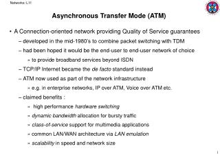
header payload Fixed length packet = cell What is ATM? • ATM is packet switching! • Switched or permanent connections • Traffic type independent (voice, data, interactive video) • Fixed length packet - 53 bytes (cell)
Voice Data Cells Video ATM Cell Relay:The Underlying Technology Cell Features Benefit Small Low latency to support real-time services like audio and video (What is an appropriate size?) Fixed Length Fast hardware switching and scalability Standardized Usable in all networks (LAN and WAN)
Without Short Cells A voice packet waits behind a large data packet
With Short Cells • Voice packet can go immediately after data packet #1 • Waiting for voice is reduced significantly
Physical Transmission Link VCs VCs VP VP VCs VCs VP VP Virtual Paths & Virtual Channels • A Virtual Path (VP) describes the semi-permanent route between two end points. • A Virtual Channel (VC) describes a cell transmission channel inside a virtual path • Unique on a link-by-link basis • Virtual channels are contained within virtual paths • Interpreted at each switch to: • determine output link • determine outgoing VPI/VCI • Two-level structure: • allows “trunking” of virtual channels as one virtual path • virtual path can be switched • both used to route cells through network
ATM switch routing Virtual Paths ATM ATM Switch Switch ATM Switch ATM ATM Switch Switch Virtual Circuits
2 1 3 ATM Switches Input Output • ATM switches translate VPI/VCI values • VPI/VCI value unique only per interface—eg: locally significant and may be re-used elsewhere in network 45 Port VPI/VCI Port VPI/VCI 1 29 2 45 29 64 2 45 1 29 1 64 3 29 3 29 1 64 29
ATM Switching • Connections (routes) set up by software • Routing (path through multiple-switch network) and resource allocation is performed once per connection by switch control CPU • Cells are switched by hardware • Hardware (table lookup + switching fabric) switches each incoming cell to appropriate output port • Once a connection is established, cells are not touched by software
VP and VC Switch • Two types of ATM switch • VP switch does not look at VCIs, switching is based on VPIs only • VCI does not change when passing through a VP switch; VPI may change • VC switch looks at both VPI and VCI • VCI (as well as VPI) may change when passing through a VC switch
ATM Protocol Stack Upper Layers ATM Adaptation Layer ATM Layer Physical Layer
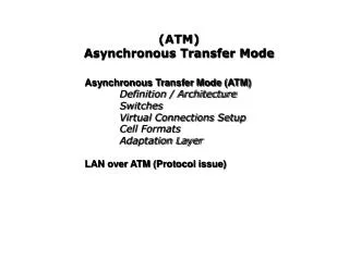
ATM Architecture Application Upper Layer Protocols Presentation Session ATM Adaptation Layer Transport Network Data Link ATM Layer Transmission-convergence physical medium dependent Physical
QUEUES and PRIORITY CBR Traffic Priority 1 VBR Traffic Priority 2 Classifier Output ABR Traffic Priority 3 Priority 4 UBR Traffic
ATM Adaptation Layer: Summary Class ServiceCategories Bit Rate ConnectionMode TimingConcern ApplicationExamples ATM Adaptation Layer (AAL) A AAL1 CBR(Constant) Connection-Oriented Yes • Bandwidth andthroughput guaranteed • Good for voice and video B AAL2 VBR(Variable)VBR-RTandVBR-NRT Connection-Oriented Yes • Best effort bandwidth and throughput • Good for live video,multimedia, LAN-to-LAN ATM Layer C AAL5 ABR(Available) Connection-Oriented No • Best effort withcongestion feedback • Reliable delivery of bursty traffic iflatency okay Physical Layer D AAL3/4 UBR(Un-specified) Connection-less No • No guarantee • For SMDS/LAN
QUALITY OF SERVICE • Max CDT, Mean CTD, CDV, CLR, CER, SECBR, CMR
Application Requirements Bandwidth • Peak Cell Rate (PCR) • Sustained Cell Rate (SCR) • Minimum Cell Rate (MCR) Delay • Cell Transfer Delay (CTD) • Cell Delay Variation (CDV) Reliability • Cell Loss Ratio (CLR) Cost ($ or Admin) • Link Weighting