Download
1 / 51
510 likes | 658 Views
ATM( Asynchronous Transfer Mode) SWITCHING Group 1. CHEN SHAN WAN WET020022 GRACE CHANG POOI KUAN WET020042 LIM SEOW FONG WET020072 NG SIAO SHAN WET020104 TAN PHAIK SEE WET020174. Content of Presentation.

E N D
ATM( Asynchronous Transfer Mode) SWITCHINGGroup 1 CHEN SHAN WAN WET020022 GRACE CHANG POOI KUAN WET020042 LIM SEOW FONG WET020072 NG SIAO SHAN WET020104 TAN PHAIK SEE WET020174
Content of Presentation • Introduction To ATM Switching And Functions of ATM Switching Grace Chang Pooi Kuan WET020042 • ATM Switching Architecture Tan Phaik See WET020174 • ATM Switching TechniquesChen Shan Wan WET020022 • Switching Element Requirements Ng Siao Shan WET020104 • Queuing Methods Lim Seow Fong WET020072
Introduction To ATM Switching And Functions of ATM Switching Grace Chang Pooi Kuan WET020042
Introduction to ATM switching • What is Asynchronous Transfer Mode (ATM) switching ?
What is ATM Switching ? • A packet switching technology that allows voice, data, image, and video traffic to be combined into evenly sized cells for high-speed transmission over one access circuit.
This means that all the information sent over an ATM network is broken down into discrete packets. • Each 53 byte cell contains 48 bytes of payload and 5 bytes of control information. • Because the cells are all the same size, cell delay at ATM switches is more predictable and manageable.
The aim of ATM switch design is to increase speed, capacity and overall performance. • ATM switching differs from conventional switching because of the high-speed interfaces (50 Mbps to 2.4 Gbps) to the switch, with switching rates up to 80 Gbps in the backplane . • ATM was designed specifically to handle broadband applications efficiently and at the same time let users give certain types of traffic priority treatment on the network.
For example, voice traffic, which cannot tolerate much delay, can be marked "high priority" with a guaranteed bandwidth and minimal delay. Less sensitive traffic, such as electronic mail, can be marked for lower priority. • ATM networks are linked together by a series of ATM switches that take in cells from various sources and switch them out again.
ATM Switch Functions • ATM switch functions : • User Plane • Control Plane • Management Plane
ATM Switch Functions • An ATM switch contains a set of input ports and output ports, through which it is interconnected to users, other switches, and other network elements.
There are 3 planes of the switching functions in the context of the Broadband Integrated Services Digital Network (B-ISDN) model : • User Plane • Control Plane • Management Plane
User Plane • The main function of an ATM switch is to relay user data cells from input ports to the appropriate output ports. • The switch processes only the cell headers and the payload is carried transparently. • As soon as the cell comes in through the input port, the Virtual Path Identifier/Virtual Channel Identifier (VPI/VCI) information is derived and used to route the cells to the appropriate output ports.
Control Plane • This plane represents functions related to the establishment and control of the Virtual Path/Virtual Channel (VP/VC) connections. • Unlike the user data cells, information in the control cells payload is not transparent to the network. The switch identifies signaling cells, and even generates some itself.
Management Plane • The management plane is concerned with monitoring the controlling the network to ensure its correct and efficient operation. • These operations can be subdivided as • fault management functions, • performance management functions, • configuration management functions, • security management functions, • accounting management • traffic management.
ATM Switching Architecture Tan Phaik See WET020174
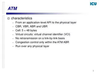
The generic module consists of the following functional blocks: Input modules, output models, cell switch fabric, connection admission control (CAC), and switch management. ATM
Input Module • The input module performs by terminates the incoming signals and extracts the ATM cell stream. • This task involves signal conversion and recovery and overhead processing. • Furthermore, the input module performs the following function on each ATM cell: • Error checking of the header information using Header Error Control (HEC) field • Determination of the destination output port • Passing signaling cells to CAC and Operations and Management (OAM) cells to Switch Management
Output Module • It prepares ATM cells into a format for transmission on the physical network. • It accomplishes this task by: • Removing and processing internal tags • Translating VPI/VCI values • Generating HEC field • Mixing CAC and Switch Management cells with outgoing cell streams • Mapping cells to physical transmission formats • Converting digital bit stream to optical signal
Cell Switch Fabric • The main task is to perform the routing of data cells, signaling and management cell. • It receives cells on an incoming port, reads the VPI/VCI value, and identifies an appropriate outgoing port for the next node that is to receive the traffic.
Connection Admission Control (CAC) • A set of procedures that include actions taken by the network to grant or deny a virtual connection. • It establishes, modifies, and terminates virtual path/virtual channel connections. • It is responsible for: • high-layer signaling protocols • interface with a signaling network
Switch Management • It has the overall responsibility of providing key information for managing the switch and the network. • It performs tasks that include the following: • Traffic management • Network Management • Security control for switch database • Customer-network management
ATM Switching Techniques Chen Shan Wan WET020022
ATM Switching Techniques • Cell Switch Fabric - to relay ATM cells as quickly as possible and accomplishes this by performing 2 major functions: • Concentration, expansion, multiplexing/demultiplexing of traffic • Routing and buffering of traffic
Five ATM Switching Alternatives : • Shared Memory Switch • Shared Bus Switch • Crossbar Switch • Multistage Switching • Banyan/Delta Switching
Switching Element Requirements Ng Siao Shan WET020104
Switching Element Requirements • The ATM switch architectures have to consider above these requirements. • Performance • Information Rates • Broadcast
Performance • Connection Blocking • Cell Loss, Cell Insertion • Switching Delay
Performance: a) Connection Blocking • Since ATM is defined to be connection oriented, after connection set-up, a logical connection must be found between the logical inlet and the logical outlet.
Cont • Connection blocking is defined as the probability that not enough resources can be found to allow all the required physical connections between inlets and outlets at any time.
Performance: b) Cell Loss, Cell Insertion • In an ATM switch it is possible that temporarily too many cells in the switch have to be transmitted through the same link (switch internal or external link). • In optimal operational conditions there is an available entry in a queue to hold all the cells. • But if the queue is currently full, another cell that will require the same queue will be lost. • The probability of a cell lost must be kept in a specified limits to assure high semantic transparency. • Some switching architectures are designed such that they will not suffer from cells competing for the same resources internally, but only at their inlets and/or outlets.
Cont • It is also possible that from some internal routing error a cell will be sent to the wrong logical connection. • If such an error occurs, error impact is doubled by the fact that one destination will miss a cell and that a second destination will accept an additional cell. • The switch element has to be designed so that cell insertion error probability will be about 1000 times better than a cell loss.
Performance: c) Switching Delay • To allow support of different real time services in an ATM network, a maximal delay has to be guaranteed and a low values of jitter. • Typical delay values are between 10 and 1000 usec, with jitter of 100 nsec or less. • The delay and the jitter in the cell are strongly related to the queueing in the switching element. A small queue will assure better delays but will increase the cell loss probability.
Information Rates • A large number of information rates have to be switched in the same ATM switch. • The maximal bit rate which a future ATM switch has to be able to switch lies around 150 Mbit/sec. • For such fast services, the switching element can be implemented as several switching elements in parallel. • Or, several 150Mbit/sec switching elements can be multiplexed on a single link. • That will require a switching rate in the order of Gbit/sec.
Broadcast • In classical connection oriented packet switching services, only point to point connections are available, because the information (cell) can be switched from one logical inlet to one logical outlet only. • In future broadband networks broadcast and multicast services are required for different applications from electronic-mail to network TV services.
Queuing Methods Lim Seow Fong WET020072
Queuing Methods: Problems • Many queuing problems in an ATM switch because: • The pre-assigned time slot concept disappears in ATM switching systems • ATM switch performs statistical multiplexing in the switch inputs • de-multiplexing in the switch outputs • For example: • Two ATM cells arrived at two inlets at the same time and are aiming for the same outlet
Queuing Methods: Approaches • Queue of waiting cells has to be implemented in the switch: • Input Buffers • Output Buffers • Central Queuing
Queuing Methods: a) Input Buffers • Add a queue at the switch element inputs • The buffers are located at the input controller (IC) • The switch interconnection network will transfer the cell from the input buffer to the output buffer without internal conditions • Arbitration logic is needed to determine which of the cells held in different inlet buffers destined to the same output will be transferred in the interconnection network
Queuing Methods: a) Input Buffers (cont’) • Solution: • The FIFO buffer can be replaced by a random access memory (RAM) • If the first cell in the queue is blocked, the next cell which is destined for an idle output (or internal switch interconnection network link) will be selected for transmission
Queuing Methods: a) Input Buffers (cont’) • The disadvantage of this solution: • A complex buffering control is required to find a cell destined to an idle connection to guarantee a correct cell sequence of cells destined for the same output. • The input buffer approach achieves the worst performance in the sense of the queue length required to achieve a given cell-loss rate in various switch loads in comparison to the other two queuing methods.
Queuing Methods: b) Output Buffers • Add a queue at the switch output • The buffers are located at the output controller (OC) of the switch element • The assumption is that many cells from the IC can cross the internal interconnection network and arrive to the outlets • This solution requires use of a very fast internal pass
Queuing Methods: b) Output Buffers (cont’) • In order to allow a non-blocking switch, the interconnection network and the output buffer have to be capable of handling N cells at one cell time (when N in the number of ICs) • When output buffers are in use, no arbitration has to be used. The control of the output is based on a simple FIFO logic
Queuing Methods: c) Central Queuing • Add a queue between the inputs on the outputs of the switch • The queuing buffers are not dedicated to a single inlet or to a single outlet, but shared between all inlets and outlets • Each coming cell will be directly stored in the central storing element • Every outlet will identify the cells destined to it in a FIFO discipline
Queuing Methods: c) Central Queuing (cont’) • Advantage: • Most efficient and required the smallest total storage to allow minimal cell loss in heavy load conditions • Since the available memory on an integrated circuit switching element is limited, it is possible to achieve low cell-loss probabilities when using the central queuing approach