Download
1 / 22
220 likes | 358 Views
The MROD. Marcello Barisonzi, Henk Boterenbrood, Rutger van der Eijk, Peter Jansweijer, Gerard Kieft, Jos Vermeulen NIKHEF, Amsterdam Adriaan K önig , Charles Timmermans, Thei Wijnen NIKHEF and Univ. of Nijmegen, Nijmegen. The Read Out Driver for the ATLAS MDT Muon Precision Chambers.

E N D
The MROD Marcello Barisonzi, Henk Boterenbrood, Rutger van der Eijk, Peter Jansweijer, Gerard Kieft, Jos Vermeulen NIKHEF, Amsterdam Adriaan König, Charles Timmermans, Thei Wijnen NIKHEF and Univ. of Nijmegen, Nijmegen The Read Out Driver for the ATLAS MDT Muon Precision Chambers ATLAS MROD Design Review
Contents • System Overview • MROD Functionality • MROD-1 Prototype • Performance Study • The next step (MROD-2) ATLAS MROD Design Review
ATLAS MDT Muon Detector ~ 300.000 Drift Tubes 1172 MDT Chambers 192 -towers of 5-8 Chambers ATLAS MROD Design Review
CSM 18 x 24 ch. TDC System Overview Chamber Tower MROD 24 ch. TDC CSM CSM-Link 18 x (GOL)* 24 ch. TDC 5 – 8 chambers 160 MBytes/s S-Link to ROB 24 ch. TDC CSM-Link (GOL) *) http://proj-gol.web.cern.ch/proj-gol ATLAS MROD Design Review
1 S 18 CSM Functionality 40 Mbit/s Data/Clock from TDC CSM Serial to Parallel & Clock Domain Separator 1 Gbit/s Separator 18 x 40 Mbit/s Data/Clock from TDC (GOL) Serial to Parallel & Clock Domain Separator 1 Start bit 32 Data bits 1 Parity bit 2 Stop bits 36 bits @ 25 ns = 900 ns 1 Separator word (S) 18 TDC data words 19 words in 900 ns 85 MB/s ATLAS MROD Design Review
MROD Functionality Separator word Check (do not store) TDC0, word 1 Compiles the original TDC data from the CSM data stream, builds event fragments end sends these to the Read Out Buffer. (tdc 1) 000…000 Skip (do not store) time TDC2, word 4 TDC3, word 2 Separator word TDC0, word 1 TDC1, word 3 TDC2, word 5 TDC3, word 3 TDC2, word 3 Separator word TDC1, word 2 TDC2, word 2 (tdc 0) 000…000 TDC1, word 1 TDC2, word 1 TDC3, word 1 TDC0, word 0 TDC1, word 0 TDC2, word 0 TDC3, word 0 ATLAS MROD Design Review
Summary of MROD Functionality • The MROD receives data from all of the 5 thru 8 MDT chambers which form one tower, from their respective CSMs via Gigabit Optical Links (GOL). • The MROD demultiplexes the TDC data from the CSMs, it builds the event fragments and it sends them to the Read Out Buffers (ROB) via an S-Link optical connection. • The max. estimated throughput at a 100 kHz level-1 trigger rate and at the full LHC design luminosity is 0.8-1.4 Gbit/s. (for details see the presentation by Charles Timmermans) • The MROD recognizes errors and exceptions in its input data streams and -- if appropriate -- informs the DCS. ATLAS MROD Design Review
MROD Form Factor • 1 MROD serves all (5 to 8) chambers of one tower. • 9 U VME64x board (single slot), 8 (or 6) CSMs in, 1 S-Link out. • • 1 MROD Crate (Sub rack) contains: • 12 MRODs (12 Segments) • 1 Crate Master with Ethernet Interface (DetDAQ) • 1 TIM: TTCrx Interface Module (incl. ROD Busy) • @ 192 towers: 192/12 = 16 MROD Crates (1 per Sector) ATLAS MROD Design Review
MROD Crate DAQ / DCS ROD Busy Network ROB ROB VME64x-bus “TIM-bus” DET-DAQ MROD … total ... 12 x MROD TIM (TTCrxInterface) CSMs CSMs From TTC system One MROD Crate services 12 towers (one full sector). In total 16 crates will be required for all MDT chambers. ATLAS MROD Design Review
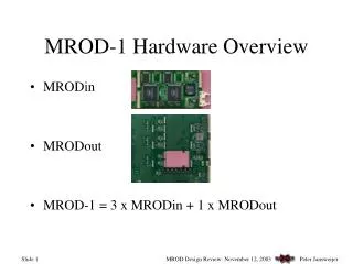
MROD-1 prototype (1) • The MROD-1 is conceived as the first full size, full speed MROD prototype, with 6 input channels (extendable to 8 input channels). • MROD-1 is built around a number of Analog Devices ADSP21160 “SHARC” DSPs. • This DSP has 6 half-duplex 40/80 Mbyte/s SHARC-links. Data transfers take place under DMA control. • The MROD-1 design relies heavily on the use of these SHARC-links. ATLAS MROD Design Review
MROD-1 prototype (2) • Modular design with three dual-input sections (MROD-ins) and one output section (MROD-out). • MROD-ins are daughter boards on MROD-out. • Main non-DSP components of the MROD-1 are FPGAs (and memories) (for details see the presentation by Peter Jansweijer) • During normal operation (i.e. in the absence of errors) the FPGAs (and memories) guarantee the speedy operation of the MROD-1. • The DSPs take care of errors and exceptions. ATLAS MROD Design Review
MROD-1 Prototype ATLAS MROD Design Review
MROD-out Board ATLAS MROD Design Review
MROD-in Board ATLAS MROD Design Review
MROD-1 in H8 (2003) • Installed MROD equipment: • 1 9U VME64x crate with special P3 back plane for TTCrx Interface Module (TIM). • 2 MROD-1s. • 1 Crate Controller Processor (Linux). • 1 TTCrx Interface Module (TIM). ATLAS MROD Design Review
ROS ROS MROD MROD 6 CSMs 6 CSMs MROD-1 crate in H8 (2003) DAQ ROD Busy Network VME-bus “TIM-bus” DET-DAQ TIM (TTCrxInterface) From TTC system ATLAS MROD Design Review
MROD-1 in H8 (start-up) • Quite a few errors (bugs) had to be corrected in the software of the SHARC DSPs. Most bugs were related to the internal MROD-1 buffer management. • Some problems with bad connections. • Emergency implementation of MROD-Busy signal was needed due to the unexpectedly low speed of the H8 read out system (the ROS). • Only one (!) single error was found in the FPGA code (firmware) of the MROD-1. ATLAS MROD Design Review
MROD-1 in H8 (summary) • MROD-1 start-up saw various problems, some of which were due to bugs and bad connections in the MROD-1 itself, some due to the down stream system. • After some weeks of painstakingly testing and debugging, the MROD-1 eventually ran stably and millions of events have been collected on a routine basis with a typical rate of1 kHz. ATLAS MROD Design Review
MROD-1 performance • The MROD-1 throughput (data and trigger rates) could not be tested in H8 due to limitations of the set-up. • A program to assess the MROD-1 has been launched at NIKHEF: • CSM output data is externally emulated in software or can be generated by dedicated CSM-like hardware. The simulated data is injected in the MROD-1 via optical links. This effort is ongoing and is intimately related to the optimization of the SHARC software. • For details and the latest results see the presentation by Jos Vermeulen. ATLAS MROD Design Review
MROD-1 Implementation Choices • Use of Gigabit Optical Link (GOL): One-way optical connection which nicely the matches the required bandwidth (19*40 Mbit/s). • Extensive use of SHARC DSPs: MROD-1 relies heavily on SHARC-links for internal data-transfer. Moreover SHARC offers easy adaptability, flexibility and testability. FPGA does not have to deal with errors and exception conditions. • Application of TTC Interface Module (TIM) by UCL. ATLAS MROD Design Review
The next MROD (MROD-2) • The MROD-2 will be fully integrated, i.e. it will consist of one single PCB VME64x module, without any daughter boards (except for the S-Link output). This eliminates a large number of connectors and thus reduces cost and enhances reliability. • The GOL receiver logic will be integrated in the MROD-in FPGAs. • The MROD-2 will have 4 MROD-ins (hence 8 inputs). • The next MROD may use a next generation DSP, the TigerSHARC. ATLAS MROD Design Review