Download
1 / 18
180 likes | 268 Views
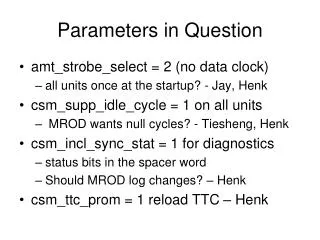
MROD: the MDT Read Out Driver. Status of MROD-1 Prototype Adriaan K önig University of Nijmegen. Contents. • System Overview • MROD-1 Prototype Status Plans • Names. TDC 1. TDC 1. CSM. CSM. 18 x. 18 x. TDC 18. TDC 18. System Overview. Chamber. Tower. MROD. CSM-Link.

E N D
MROD: the MDT Read Out Driver Status of MROD-1 Prototype Adriaan König University of Nijmegen ATLAS Muon Electronics Meeting
Contents • System Overview • MROD-1 Prototype Status Plans • Names ATLAS Muon Electronics Meeting
TDC 1 TDC 1 CSM CSM 18 x 18 x TDC 18 TDC 18 System Overview Chamber Tower MROD CSM-Link 6 x S-Link to ROB CSM-Link ATLAS Muon Electronics Meeting
1 S 18 CSM-MUX Functionality 40 Mbit/s Data/Strobe from TDC CSM-MUX Serial to Parallel & Clock Domain Separator 1 Gbit/s Separator 18 x 40 Mbit/s Data/Strobe from TDC (CSM-Link) Serial to Parallel & Clock Domain Separator 1 Start bit 32 Data bits 1 Parity bit 1 Stop bit 35 bits @ 25 ns = 875 ns 1 Separator word (S) 18 TDC data words 19 words in 875 ns 87 MB/s ATLAS Muon Electronics Meeting
MROD Functionality Separator word Check (do not store) TDC0, word 1 Build events in a partitioned memory from TDC data fragments (tdc 1) 000…000 Skip (do not store) time TDC2, word 4 TDC3, word 2 Separator word TDC0, word 1 TDC1, word 3 TDC2, word 5 TDC3, word 3 TDC2, word 3 Separator word TDC1, word 2 TDC2, word 2 (tdc 0) 000…000 TDC1, word 1 TDC2, word 1 TDC3, word 1 TDC0, word 0 TDC1, word 0 TDC2, word 0 TDC3, word 0 ATLAS Muon Electronics Meeting
CSM-Link CSM-Link CSM-Link CSM-Link CSM-Link CSM-Link MROD Throughput MROD MROD-in MROD-out MROD-in S-Link MROD-in Average 5 hits per TDC + header + trailer = 7 words/event Per tower of 6 chambers max. 88 TDCs * 7 600 words/event (= 2.4 kB/event) Worst case est.: @ 100 kHz L1A rate 240 MB/s per MROD Calculation based on actual tower layout (J.Chapman): max. rate < 60 MB/s per MROD ATLAS Muon Electronics Meeting
MROD Form Factor • • 9 U VME board (single slot), 6 CSM Inputs, 1 S-Link Output • • Optionally 2 extra CSM Inputs with “extension” board to • accommodate some special towers with > 6 chambers • CSM Input Interfaces integrated on main board • • 1 MROD Crate (Sub rack) contains: • 12 MRODs (12 Segments) • Up to 4 MROD extension boards • 1 Crate Master with Ethernet Interface (DetDAQ) • 1 TIM: TTC-Rx Interface Module (incl. ROD Busy) • • @ 192 towers: 192/12 = 16 MROD Crates (1 per Sector) ATLAS Muon Electronics Meeting
MROD Crate DAQ / DCS ROD Busy Network ROB ROB VME-bus “TIM-bus” LDAQ MROD … total ... 12 x MROD TTCrxInterface Module 6 CSMs 6 CSMs From TTC system One MROD Crate services 12 towers (e.g. one full sector). In total 16 crates will be required for all MDT chambers. Some MRODs may have 7 or 8 input links via “slave” MROD input cards. ATLAS Muon Electronics Meeting
Memory FPGA MROD-1Prototype SHARC VME64x FPGA Memory SHARC (2x) SharcLinks 3x (intotal) Memory FPGA TTC Interface SHARC FPGA Memory ATLAS Muon Electronics Meeting
MROD-1 Prototype Form Factor • • 9 U VME boards, 2 units wide • 1 S-Link output on daughter board • 6 S-Link inputs on daughter boards • • SHARC II (ADSP21160) DSPs: • (3 for input, 2 for output processing) • Altera APEX FPGAs, 200k gates • TIM bus over special P3 back plane • VME64x interface S-Link daughter boards Input Input Input Output Motherboard ATLAS Muon Electronics Meeting
MROD-1 Prototype Status • MROD-1 module exists. • FPGA code has been tested, debugged and verified. • Quite a few problems with SHARC-II DSPs: work-arounds being implemented; testing continues. • More MROD-1 modules will be available soon. • More software tools are being developed. ATLAS Muon Electronics Meeting
MROD-in board ATLAS Muon Electronics Meeting
MROD-out board ATLAS Muon Electronics Meeting
MROD-in power-up modification ATLAS Muon Electronics Meeting
Detail power-up modification ATLAS Muon Electronics Meeting
MROD-1 Prototype Plans • Read out of BOL chambers in NIKHEF cosmic ray test stand with TDC32 chips and special CSM-MUX. • Read out of BOL test stand chamber @ NIKHEF with ASD mezzanine cards through CSM adapter box and special CSM-MUX. • Direct read out of ASD mezzanine cards with “final” CSM and MROD-1 with CSM-Link interface (“next” MROD-1 prototype). ATLAS Muon Electronics Meeting
Next MROD-1 Prototype CSM-Link daughter boards • • Same 9 U VME board, 2 units wide • 1 S-Link output on daughter board • 6 CSM-Link inputs on daughter boards • Reprogramming of MROD-in FPGAs Input Input S-Link daughter board Input Output Motherboard ATLAS Muon Electronics Meeting
MROD Names (NIKHEF and Univ.of Nijmegen) • Marcello Barisonzi • Henk Boterenbrood • Jasper Hendriks • Peter Jansweijer • Gerard Kieft • Adriaan König • Jos Vermeulen • Thei Wijnen ATLAS Muon Electronics Meeting