Download
1 / 61
610 likes | 777 Views
MKP-I: Impedance considerations. C. Zannini , H. Bartosik , G. Rumolo , B. Salvant M. Barnes, T. Kramer, L. Sermeus. Overview. Simulation model Simulation results Proposed options Beam coupling impedance considerations Transverse impedance Longitudinal impedance Shielding

E N D
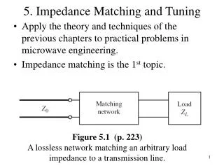
MKP-I: Impedance considerations C. Zannini, H. Bartosik, G. Rumolo, B. Salvant M. Barnes, T. Kramer, L. Sermeus
Overview • Simulation model • Simulation results • Proposed options • Beam coupling impedance considerations • Transverse impedance • Longitudinal impedance • Shielding • Beam induced power loss and transverse stability • Beam induced power loss • Transverse stability considerations • Beam coupling impedance with beam out
Overview • Simulation model • Simulation results • Proposed options • Beam coupling impedance considerations • Transverse impedance • Longitudinal impedance • Shielding • Beam induced power loss and transverse stability • Beam induced power loss • Transverse stability considerations • Beam coupling impedance with beam out
Proposed options sd xbeam
Beam coupling impedance of the proposed options Option 3 and Option4 result the more convenient solutions
Overview • Simulation model • Simulation results • Proposed options • Beam coupling impedance considerations • Transverse impedance • Longitudinal impedance • Shielding • Beam induced power loss and transverse stability • Beam induced power loss • Transverse stability considerations • Beam coupling impedance with beam out
SPS transverse impedance budget Vertical impedance: Comparison between present MKPs and MKP-I system The new MKP-I system has a slightly larger vertical impedance per meter length Smaller vertical aperture and shorter magnet length
SPS transverse impedance budget Vertical impedance: Comparison between present MKPs and MKP-I system The new MKP-I system has a slightly larger vertical impedance per meter length Smaller vertical aperture and shorter magnet length
SPS transverse impedance budget MKP-I system would significantly increase the vertical impedance of SPS kickers
SPS transverse impedance budget MKP-I system would significantly increase the vertical impedance of SPS kickers
Overview • Simulation model • Simulation results • Proposed options • Beam coupling impedance considerations • Transverse impedance • Longitudinal impedance • Shielding • Beam induced power loss and transverse stability • Beam induced power loss • Transverse stability considerations • Beam coupling impedance with beam out
SPS longitudinal impedance Comparison between present MKPs and MKP-I system The new MKP-I system has a slightly larger vertical impedance per meter length Smaller vertical aperture and shorter magnet length
SPS longitudinal impedance Comparison between present MKPs and MKP-I system The new MKP-I system has a slightly larger vertical impedance per meter length Smaller vertical aperture and shorter magnet length
SPS longitudinal impedance MKP-I system would significantly increase the longitudinal impedance of SPS kickers
SPS longitudinal impedance Comparison between present SPS kickers and MKP-I system MKP-I system would significantly increase the longitudinal impedance of SPS kickers
Overview • Simulation model • Simulation results • Proposed options • Beam coupling impedance considerations • Transverse impedance • Longitudinal impedance • Shielding • Beam induced power loss and transverse stability • Beam induced power loss • Transverse stability considerations • Beam coupling impedance with beam out
Shielding: proposed options M. Barnes, T. Kramer, L. Sermeus G. Iadarola, G. Rumolo For electron cloud mitigation it is strongly recommended that the beam does not see the ceramic (see MKIs in LHC)
Overview • Simulation model • Simulation results • Proposed options • Beam coupling impedance considerations • Transverse impedance • Longitudinal impedance • Shielding • Beam induced power loss and transverse stability • Beam induced power loss • Transverse stability considerations • Beam coupling impedance with beam out
Beam induced power loss Beam induced heating The calculations for MKEs have been successfully benchmarked against beam induced heating observations during 2012
Beam induced power loss Beam induced heating Present MKPs could strongly suffer of beam induced heating with high intensity beam
Beam induced power loss Beam induced heating Present MKPs could strongly suffer of beam induced heating with high intensity beam Even worst for MKP-I
Beam induced power loss Beam induced heating The shielding option (ceramic plate with titanium coating is not very efficient to reduce the beam induced power loss)
Overview • Simulation model • Simulation results • Proposed options • Beam coupling impedance considerations • Transverse impedance • Longitudinal impedance • Shielding • Beam induced power loss and transverse stability • Beam induced power loss • Transverse stability considerations • Beam coupling impedance with beam out
Transverse stability: Q20 MKP-I option3 wake model HEADTAIL simulation Transverse stability Present wake model reproduces the instability behavior (PhD thesis of H. Bartosik, to be published) HEADTAIL simulations from H. Bartosik The new MKP-I kicker system would reduce the transverse vertical instability threshold of ≈ 5%
Overview • Simulation model • Simulation results • Proposed options • Beam coupling impedance considerations • Transverse impedance • Longitudinal impedance • Shielding • Beam induced power loss and transverse stability • Beam induced power loss • Transverse stability considerations • Beam coupling impedance with beam out
Longitudinal impedance: beam out xout Having the circulating beam out of the magnet would dramatically reduce the impedance
Transverse impedance: beam out xout Having the circulating beam out of the magnet would dramatically reduce the impedance
Info from Benoit : very preliminary studies for the septum • Preliminary design provided by Bruno Balhan last week • Coarse approximations had to be made due to the complexity of the device, and lack of available information: • Laminations replaced by ferrites 4A4 • Longitudinal segmentation ignored • Magnetic laminations are partially shielded by steel holders • Several significant undamped longitudinal modes from 50 MHz onwards (i.e. fully in the beam spectrum) • Very large upstream and downstream aperture (frequencies above 500 MHz will escape in the beam pipe) • The impedance of this septum should be fully checked and it is likely that it should be optimized
Summary and conclusions • The unshielded MKP-I would significantly contribute both to the longitudinal and transverse SPS beam coupling impedance. • A reduction of about 5% of the transverse instability threshold has been estimated. • The MKP-I with the present design could limit future operation with 25 ns beams due to the beam induced heating (similarly to the non-serigraphedMKE in 2012). • Circulating beam out would dramatically reduce both longitudinal and transverse impedance solving both heating and stability issues. • Preliminary simulations seems to indicate that the shielding option (ceramic plate with titanium coating) is not very efficient to reduce the beam induced heating.
SPS transverse impedance budget Vertical impedance: Comparison between present MKPs and MKP-I system
SPS transverse impedance budget Vertical impedance: Comparison between present MKPs and MKP-I system
SPS longitudinal impedance Comparison between present MKPs and MKP-I system
SPS longitudinal impedance Comparison between present MKPs and MKP-I system
Effect of magnet length For a given cell length and total magnetic length in terms of beam coupling impedance a smaller number of magnets is more convenient
Effect of magnet length For a given cell length and total magnetic length in terms of beam coupling impedance a smaller number of magnets is more convenient
Effect of magnet length For a given cell length and total magnetic length in terms of beam coupling impedance a smaller number of magnets is more convenient
Effect of magnet length For a given cell length and total magnetic length in terms of beam coupling impedance a smaller number of magnets is more convenient
Effect of the beam position [mm] The broadband peak due to the ferrite decreases as the beam get closer to the inner conductor The peak due to the TEM mode increases as the beam get closer to the inner conductor