Download
1 / 27
270 likes | 372 Views
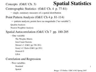
Pulsed holographic interferometry with photorefractive crystals. Recent advances of the european “PHIFE” project. Marc GEORGES , Philippe C. LEMAIRE , Centre Spatial de Liège, Angleur (B) Gilles PAULIAT, Gérald ROOSEN Laboratoire Charles Fabry de l ’Institut d ’Optique, Orsay (F)

E N D
Pulsed holographic interferometry with photorefractive crystals. Recent advances of the european “PHIFE” project Marc GEORGES, Philippe C. LEMAIRE, Centre Spatial de Liège, Angleur (B) Gilles PAULIAT, Gérald ROOSEN Laboratoire Charles Fabry de l ’Institut d ’Optique, Orsay (F) Igor ALEXENKO, Giancarlo PEDRINI, Institut für Technische Optik, Stuttgart (D) Sébastien RYHON, OPTRION S.A., Liège (B)
Summary • Photorefractive effect • Definition • Application to holographic interferometry • cw Photorefractive holographic camera • applied to vibration • Pulsed system • applied to vibration • discussion : drawback lead to PHIFE project • PHIFE project • goals • partnership • laboratory studies • present/future work
Photorefractive Effect 2. Charges generated by photo-excitation in illuminated area, migrate and are trapped in dark area 1. Fringe pattern created by interference between 2 waves 3. Local space charge field Pockels effect 4. Modulation of refractive index Dn THICK PHASE HOLOGRAM
Photorefractive Effect • PR effect is dynamic and reversible Interferogram 1 Object state 0 Object state 2 Object state 1 incident Interferogram 2 diffracted cw lasers • Recording energy at saturation : Es = t.I pulsed lasers • Diffraction efficiency : h = Idiff/Iref ~ (Dn)2 • Dn = Dnsat (1-exp(-t/t)) • Application to holographic interferometry interference between diffracted beam (reference object state) transmitted beam (deformed object state)
record readout CCD emptied Photorefractive Effect • Application to pulse holographic interferometry • First pulse : • Hologram recording • object state 0 • Second pulse : • Hologram readout • object state 1 • Interferogram showing (state 1 - state 0)
Photorefractive crystals Sillenite Bi12SiO20 (BSO) High sensitivity : ES ~ 1-10 mJ/cm2 Poorest efficiency : h~ 0.1 % Visible (blue-green) Ferroelectrics LiNbO3, BaTiO3 Poor sensitivity : ES ~ 1 J/cm2 Highest efficiency : h~ 100 % Semiconductors CdTe, GaAs Highest sensitivity : ES ~ 0.1-1 mJ/cm2 Poor efficiency : h~ 1 % NIR (l=1 µm)
Photorefractive effect • Particular properties : depend on crystal cut Anisotropic diffraction Isotropic diffraction Interferogram contrast depends on the analyser orientation Interferogram contrast depends on the product : -coupling constant -crystal thickness
Cw Holographic Camera • Developed by CSL : 1993-1998 • Optical head : L=25 cm, 1 kg • Laser : DPSS, VERDI 5W • Laser light brought by optical fiber • Specialty fiber developed (5 m, Transmission 80%, 5W injected) • Quantification of displacements : • Phase-shifting • Carrier fringes with FFT • Response time : • 5-10 seconds • can be tuned by reference beam intensity • Now commercialized by spin-off OPTRION
Cw Holographic Camera • Applications : Stroboscopic Real-Time
Pulsed experiments • Developments since 1998 (CSL and LCFIO) • Use Q-switch YAG laser (COHERENT Infinity) frequency doubled : 532 nm (adapted to sillenite crystals) pulses : 3 ns energies : 0 to 400 mJ/pulse repetition rate : 0,1 to 30 Hz • Photorefractive crystal under isotropic diffraction process
Pulsed experiments • Pulse 1 : all energy used for the recording • Pulse 2 : readout • decrease Eobj to avoid CCD blooming • decrease Eref to not erase the hologram • Phase f measurement : • Cam 1 : I = I01 (1+m sin f) • Cam 2 : I = I02 (1+m cos f)
Pulsed experiments • Application to vibrations : 4 pulse technique Amplitude of the frequency response in 2 points
Pulsed experiments • Drawbacks : • Use of single-pulse laser (tricky synchronization) • Energy balance between pulses • Change of polarization state of reference beam at readout (Pockels cell) • Improvements : • Use of double-pulse lasers • Different pulse energies • Passive change of polarization state • PHIFE project started end 2001
PHIFE • Pulsed Holographic Interferometer for the analysis of Fast Events • Goal : Develop a holographic camera • giving high resolution results typical of PRCs • working with double-pulse YAG Q-switch laser • 25 Hz repetition rate • energies 800 mJ (1064 nm) and 350 mJ (532 nm) • variable delays (down to 10 microseconds) • provides phase quantified data • integrated to the laser head (single box) • adapted or adaptable to different applications : • solid objects (vibrations, shocks, …) • transparent objects (aerodynamic studies in windtunels)
record readout CCD emptied PHIFE • Development of holographic heads • “Real-time” systems based on double-pulse lasers • 1064 nm : CdTe/AsGa • 532 nm : Bi12SiO20 • Phase quantification techniques • obtain a processable interferogram on a single pulse • Techniques possible : • Phase-shifting (multi-camera) • FFT + carrier fringe (single-frame analysis) • others
PHIFE • Partners : • Dantec Ettemeyer (co-ordinator, D) : Final integrator • Centre Spatial de Liège (B) : Laboratory developments (532 nm) • Laboratoire Charles Fabry de l ’Institut d ’Optique, Orsay (F) : Laboratory developments (1064 nm) • Institut für Technische Optik, Stuttgart (D) • CCD triggering system and fast frame grabber • Phase processing algorithms • Innolas, (UK, D) : Double-pulse single-cavity laser development • Optrion, Liège (B) : Industrial Holographic head development • Amitronics, Seefeld (D) : Industrial end-user (vibrations) • European Transonic Windtunel, Köln (D, UK, F, NL) : Industrial end-user (aerodynamics)
PHIFE • Laboratory experiments (cw YAG lasers) • Different wavelengths • 532 nm : Bi12SiO20 • 1064 nm : AsGa - CdTe • Different crystal configurations (anisotropic vs. isotropic) • Same object - same field - same illumination power • Anisotropic diffraction : better contrast - lower light level • Isotropic diffraction : no output polarizer - more light - larger objects Choice : anisotropic - better quality - phase quantification easier ISOTROPIC ANISOTROPIC
PHIFE • Different recording geometries • Classical “co-propagating” geometry • Novel “90°-geometry”
PHIFE • 90° geometry • BSO crystal at 532 nm : Optical Activity • AsGa crystal at 1064 nm : No Optical activity
PHIFE • Phase-shifting with multi-camera system • Cam 1 : I = I01 (1+m sin f) • Cam 2 : I = I02 (1+m cos f)
PHIFE • FFT single frame processing with carrier fringes • carrier obtained by active techniques : • moving optical elements between pulses • Not possible or very difficult due to short delays • carrier obtained with new patented technique (LCFIO) : • 2 orthogonal polarisations (anisotropic diffraction) • Birefringent plate after the crystal • Phase shift between two orthogonal polarisations • Phase shift proportional to beam transverse coordinates • Result : rectilinear fringes
PHIFE • FFT single frame processing with carrier fringes • Demonstration in cw regime, response time typ. 500 ms
PHIFE • FFT single frame processing with carrier fringes • Larger object CARRIER + OBJECT DISPLACEMENT PHASE AFTER FFT PROCESSING CARRIER
PHIFE • Prototype building : choice of best configurations/geometries • Modular design • 2 crystals considered • Bi12SiO20 (anisotropy - co-propagating) • AsGa (anisotropy - 90°) • 2 phase quantification techniques • 2-camera system (with both AsGa - Bi12SiO20) • FFT with carrier fringes (only with AsGa)
PHIFE • CAD views by Optrion
PHIFE • Present-future work : • Integration of industrial holographic head • Integration of holographic head with laser • Integration of software • Validation on known cases (with counter-measurements) • Industrial tests • Vibrations,… • Aerodynamics