Download
1 / 12
120 likes | 224 Views
Sub-mm period microundulator to produce 150eV photons. Using a micro fabricated undulator to bridge the four decade gap between regular pure permanent magnet undulators and inverse Compton scattering sources Finn O’shea UCLA 04/27/2012. Outline.

E N D
Sub-mm period microundulator to produce 150eV photons Using a micro fabricated undulator to bridge the four decade gap between regular pure permanent magnet undulators and inverse Compton scattering sources Finn O’shea UCLA 04/27/2012
Outline The gap between visible light and hard x-rays Microundulator Parameters Why ATF? Proposed experiment
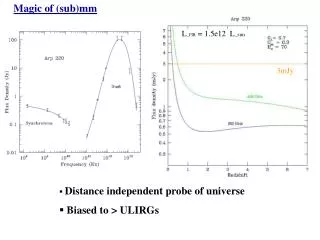
Photons with 80 MeV beam 1 cm period undulator will produce visible light 10 micron laser ICS will produce hard x-rays Gap is currently filled by changing the beam energy The problem scales with beam energy – the four missing decades can only be filled by changing beam energy Microundulator bridges this gap 1 cm undulator 10 micron ICS 400 micron undulator
Simulation Profile Taken from UF kickoff presentation (01/26/2012) Period: 400 µm Magnet width: 200 µm Magnet thickness: 500 µm Magnet length: 2000 µm Side Bar width: 200 µm 50 periods long (2 cm) Material: laser cut NdFeB
Magnetic Properties 0.3 T on axis peak field 50 T/m gradient due to side bars Current design limits maximum field, increase M to get more field.
Benefits • Besides the coverage of the missing decades… • High peak brightness • 2 1020 maximum brightness (diffraction limited) • Experimental: 2 1016 ph/(mm2 mrad2 0.1% shot) • “Classical” permanent magnet designs are well understood • More exotic designs (APPLE, DELTA) to allow polarization control • kHz switching (wavelength polarization) in the soft x-ray regime that doesn’t currently exist at synchrotrons (force mitigation) • Cheap “disposable” undulators?
“Known unknowns” • Unknown field quality • Can assembly be controlled well enough to get good field quality? • Low K ~ 10-2, but scales well to mm period (K ~ 0.1 @ 2 mm) • Wake fields • Might be a problem for high current beams • Demagnetization • Cooling?
Why ATF? • ATF has all the right stuff to test this technology: • Low energy electron beam which does not typically create photons in the soft x-ray regime (GeV machines usually) • Experience creating small, large aspect ratio electron beams for a 200 micron gap • Ready Infrastructure: • Detection efficiency – MCP was designed for this energy range (40% efficiency) • Beam positioning – tried and true methods on beam line 2
Experimental Layout MCP is installed at the end of the straight section Undulator is installed in the Cerenkov wakes holder Optional: Multilayer used to filter 120 eV photons and direct them from directly downstream (noise suppression)
Experimental Goals • Pulse wire measurement of 2nd integral of the undulator (field quality) • 1st integral probably wont work without interferometer • Simulation: Iy= 3.5 10-2 T mm -> 150 microradians • IIy = 70 T mm2 -> 3 microns • Assess photon production ability • Photon counting on MCP (1 week) • Multilayer -> Bandwidth measurement (1 add. week) • Pulse wire after for damage
Summary New technology that has features that current insertion devices cannot provide at ~100 MeV Accesses a new photon regime at ATF: soft x-rays Infrastructure already exists to do the experiment
EUVL P = 12 mW/A (beam current) @ 150 eV with 100 periods (1% bandwidth – 1/Np) FODO type lattice for increased # of periods? Opening angle goes like 1/(gamma sqrt(Np)) for good quality undulator