Download
1 / 26
260 likes | 634 Views
GPS Rover. Travis Gruber Phil Treddenick Matt Kennedy Marcin Skirucha. Overview. Rover Features Overall System Block Diagram Parts Listing Peripherals System Board Software Schedule Division of Labor. Rover Features. User Friendly GUI On-The-Fly Waypoint Selection

E N D
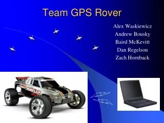
GPS Rover Travis Gruber Phil Treddenick Matt Kennedy Marcin Skirucha
Overview • Rover Features • Overall System Block Diagram • Parts Listing • Peripherals • System Board • Software • Schedule • Division of Labor
Rover Features • User Friendly GUI • On-The-Fly Waypoint Selection • Remote Shutdown • Multi-Speed Selection • Integrated Collision & Inclination Detection • Waypoint Backtracking upon collision
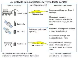
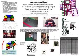
System Block Diagram ADC ADC 68HC11 A/D Various IO Pins RS232 Drive Servo DAC Inclinometer Collision detectors Motor Servo DAC Terminal RS232 System Memory RF transmitter Digital Compass RF receiver RS232 Time/ Div Mux GPS
Parts Listing System Board Components MC68HC11 MCU EPROM SRAM Xilinkx FPGA Jtag interface Bidirectional Transceiver Transparent Latches 5V Voltage Regulator SPDT Reset Switch Maxim RS232 Driver SiPs DACs, ADCs Various TTL logic Peripherals Traxxas RC Car Body Futaba Remote and Servos Trimble AgGPS 124/132 Locator Digital Compass T2 Inclinometer 8.2 V NiCad Battery Pack 8.2V NiCad battery for embedded board Limit Switch Serial RF Receiver/Transmitter Digital Camera
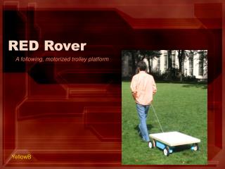
Peripherals – Rover Chassis • Fiber Composite Chassis • High Torque 20-Turn Motor • Rotary 3-Speed Control • 12.25” Front and Rear Track • Adjustable Gear Ratio • Steering Servo • 3.2kg-cm Torque • 0.223sec/60 degree
Universal Servo Param’s Vbat =8.2V Vpower =6.2V fservo =52.08Hz pservo =20ms Vp-p =5.7V Steering Servo Duty Cycles Dneutral =8.2% Dleft-MAX =10.4% Dright-MAX =5.9% Peripherals – Servo Interface Drive Servo Duty Cycles Dneutral =7.8% DMAX =10.4% DMIN =5.7%
Trimble AgGPS 124/132 Receiver Specs: Size: 14.5cm W * 5.1cm H * 19.5cm D Weight: 0.76 Kk (1.68lb) Power: 7 Watts (max), 10-32V DC Antenna Specs Size: 15.5 cm D * 14cm H Weight: 0.55Kg (1.2lb) Peripherals - GPS
Peripherals – GPS Channels • General • 12-channel, parallel tracking L1 C/A code and carrier phase filtered measurements and multi-bit digitizer • Update Rate • 1 Hz standard; 10Hz optional • Differential Speed Accuracy • 0.1MPH (0.16KPH) • Differential Position Accuracy • Less than 1 meter horizontal RMS; At least 5 Satellites, PDOP < 4 and RTCM SC-104 standard format broadcast form Trimble 4000RSI or equivalent reference station • Time to first Fix • < 30sec (typical) • NMEA Messages • ALM, GGA, GGL, GSA, GSV, MSS, RMC, VTG, ZDA
Peripherals – Limit Switch • 2XC12 Enclosed Snap Action Limit Switch • Actuator Short Roller • Size • 0.69in D * 0.95in H * 1.94in L • Max Pretravel • 0.106in • Overtravel • 0.064in • Operating Force • 8.8-12.3oz
Peripherals - Inclinometer • T2 Incremental Inclinometer • 2-channel quadrature outputs • 3rd channel index option • TTL compatible • -40 to +100°C operating temperature • Single +5V supply • 360° range • 3600 codes/rev. (900 CPR) = 0.1° resolution
Peripherals – Digital Compass • 1490 Digital Compass • Power • 5-18 volts DC @ 30 ma • Outputs • Open collector NPN, sink 25 ma per direction • Weight • 2.25 grams • Size • 12.7 mm diameter, 16 mm tall • Pins • 3 pins on 4 sides on .050 centers • Temp • -20 to +85 degrees C
Quatech QTM-8524 RF Transceiver • Power • 10-30 volts DC • Features • Up to 500 m range with open line of sight • Supports baud rates from 600bps-57.6kbps • Supports RS-232 • Has TxD and RxD pins • Requires external antenna, also provided by Quatech
Digital Camera • KB Gear Jamcam V 3.0 • System Specs • 640 X 480 Max Resolution • Serial Output with RS-232 Communications • Stores up to 8 photos at 640 X 480 and 28 photos at 320 X 240
System Schematics • Microcontroller
System Schematics • Bus Drivers
System Schematics • FPGA and EPROM
Memory Map • 64 byte Register Block moved to 0000h • 512 byte Internal RAM moved to 7000h • External NVRAM mapped to 5000h • EEPROM removed from B600h • Memory Mapped IO at 1000h to 4FFFh
Current Status • Successful Program Fetch and Execution • NOP NOP NOP JMP • Integrated Xilinx FPGA • Debugging various chip selects • Boot Monitor
Workstation GUI • Send kill command • View current waypoints • Set new waypoints • Store waypoint history • View waypoint history
Matt Finishing Board GPS Communications Marcin Finishing Board Inclinometer Digital Compass Camera Travis RF Communications Limit Switch Phil Servo control implementation GUI Interface Division of Labor
Conclusions • Choices about Peripherals • Progress so far • Places where we anticipate the most difficulty • Any Questions?