Download
1 / 57
660 likes | 1.32k Views
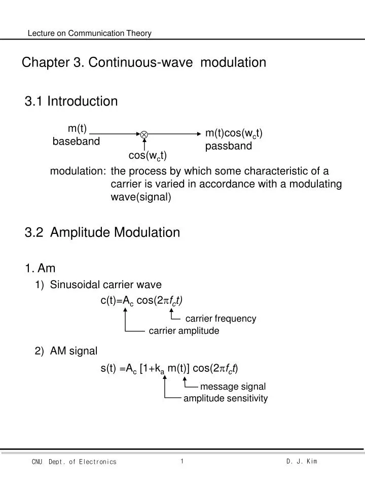
carrier frequency. message signal. Chapter 3. Continuous-wave modulation. 3.1 Introduction modulation: the process by which some characteristic of a carrier is varied in accordance with a modulating wave(signal) 3.2 Amplitude Modulation 1. Am 1) Sinusoidal carrier wave

E N D
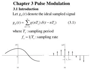
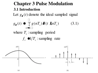
carrier frequency message signal Chapter 3. Continuous-wave modulation • 3.1 Introduction • modulation: the process by which some characteristic of a carrier is varied in accordance with a modulating wave(signal) • 3.2 Amplitude Modulation • 1. Am • 1) Sinusoidal carrier wave • c(t)=Ac cos(2fct) • 2) AM signal • s(t) =Ac [1+ka m(t)] cos(2fct) m(t) baseband m(t)cos(wct) passband cos(wct) carrier amplitude amplitude sensitivity
3) s(t) 의 envelop 이 m(t)와 똑같은 shape이 될 조건 a) | Kam(t) | < 1 for all t b) fc >> W where W is message BW
BT=2W • 4) 주파수상에서의 표현 ex1) Single-Tone Modulator • message m(t)=Am cos(2fmt ) • AM s(t)=Ac [1+cos(2fm t)]cos(2fct) • Where = kaAm ; Modulation factor • 100 = 100 kaAm ; percentage Modulation
m(t) BPF[v2(t)] • 2. Switching Modulation • v1(t) = Accos(2(t)) + m(t)) • If m(t) Ac • v2(t) v1(t), c(t) > 0 • 0, c(t) <0 • v2(t) [AC cos(2(t)) + m(t))] gTo(t) • where T0=1/fc
Diode function • By Fourier series on off
3. Envelope Detector : AM radio receiver Charging time constant = (f + RS ) C For Rapid charge (f + RS )C << 1/fc Discharging time constant =
3.3 Virtues, Limitations , and Modifications of AM • 1. Virtues • 1) easy modulator: switching mod, square-law modulator • demodulator: envelop detector, square-law detector • 2) relatively cheap • 2. Limitations • 1) Wasteful of power carrier power • 2) Wasteful of BW 1/2로 줄일 수 있다. LSB와 USB가 symmetry. • 3. Modifications of AM • 1) DSB-SC modulation : no carrier • 2) VSB modulation : BW를 약 1/2로 • 3) SSB modulation : BW를 1/2로
3.4 DSB - SC Modulation • 1. DSB - SC signal
s(t)=m(t) c(t) > 0 s(t)= -m(t) c(t) < 0 • 2. Ring Modulator + -
M(f) w -3fc fc 3fc -fc S(f) -3fc 2W 2W • c(t) = • BPF[s(t)] =BPF[c(t)m(t)] f=fc • = m(t) • (주의점) Transformers are perfectly balanced and diodes are identical no leakage of modulation frequency into modulator output
Local Osc = + LPF • 3. Coherent detection or synchronous demodulation • frequency coherent detection
f -2fc 2fc 2w 2w • Coherent Detection 특징 : perfect demodulation • but 복잡 cost • 4. Costas Receiver V(f)
s(t) OSC 빠른 주파수 450 - 450 늦은 주파수 정상주파수
Quadrature In-phase • 5. Quadrature-Carrier Multiplexing or QAM
Key points> Correct phase & frequency • Costas Receiver 사용 • Send a pilot signal outside the passband of the modulated signal • Pilot : Low power sinusoidal tone whose frequency and phase are related to c(t) • Add pilot signal of small carrier • 3.5 Filtering of side-bands <Band pass filtering>
H(f) f fc -fc 0 FILTER Hi(T) LPF m(t) s(t) m(t) FILTER HQ(T) -fc fc • 1.BPF의 LSB와 USB가 symmetric 할 경우 • 2. BPF의 LSB와 USB가 unsymmetric 할 경우
HI(f) : symmetric component fc -fc +jHQ(f) HI(f) -fc fc jHQ(f) fc • SSB & VSB
HI 1 HQ 0.5 f fc-fv fc+fv fc+W fc HI 1 0.5 f fc+fv fc-fv fc-W HQ fc 3.6 Vestigial Side-Band Modulation • 1. Filtering • 1) fc를 중심으로 odd-symmetry • LSB(or USB)의 vestige만 보냄. • 2) USB or LSB
3.58 MHz color • 2.Television Signals • 1)TV 신호의 특징 a)Video 신호가 large BW 대부분의 energy가 low-frequency에 b)수신기가 간단, cheap use envelope detection • 2)주파수 특성
due to cheap negligible distortion • 3. 0.75 MHz (25%)의 LSB를 full scale로 보내는 이유 • Envelope detection에서 waveform distortion을 줄이기 위해 • 1) Waveform distortion add carrier component to apply envelope detector • Envelop detector output • 2) m’(t)에 의한 distortion을 줄이는 방법 a) ka를 줄인다. b) Vestigial sideband의 폭을 늘인다. • 3) TV 신호에서의 해법 a) 100% percentage modulation b) 0.75MHz의 LSB
3.7 SSB • 1. 방법 : USB 나 LSB만 전송 • 2. 이유 : Message m(t)가 실수 M(f)는 conjugate symmetric • 3. 문제점 : LSB나 USB가 붙어 있을 경우 filtering이 어렵다. • 4. 적용분야 : Message spectrum이 origin에서 energy gap이 있을 때 • ex) Voice (-3400 ~ -300) (300 ~ 3400Hz)
BPF m(t) USB f fc fc+W 0 -f1 f1 0 easy BPF f2 -f2 f2+f1 • 5. Pass-band에서 BPF로 구현 • BPF : highly selective filters ( 예:Crystal resonator) • Multiple modulation으로 구현
HI(f) jH Q(f) m(t) OSC s(t) -900 H.T • 6. Time Domain Description of SSB (Baseband에서 구현) • Hartley modulator
LPF s(t) -900 LPF • 7. Demodulation of SSB signal • 1) 구현 • 2) Coherent detector : both in phase & in frequency a) Low-power 의 pilot carrier를 전송 b) Highly stable oscillator 사용 still phase error • 3) Phase error 가 있을 경우 • Phase distortion Voice insensitive to phase error Donald Duck voice effect Music or Video unacceptable
TV f3 f5 f1 DTV f4 f2 3.8 Frequency Translation f3 = f2 + f1 f5 = f4 + f3= f4 (f2 f1) = f4(f2-f1) f4(f2+f1) • Upward • Downward • ex) f1= 0M f2= 44M f3 = 44M f4= 66M f5 = 110M, 22M • ex) f1=110M f2= 1030M f3 = 920M, 1140M f4= 876M f5 = 44M, 1796M f6= 44M f7 = 0M, 88M
w1 w1 w2 w2 wn wn f w1 w2 w3 wn 3.9 Frequency-Division Multiplexing • ex2) Voice BW= 4kHz, SSB • Basic Groups=12 Voice, fc=60+4nkHz. n=1~12 • Super Groups= 5Basic Groups, fc=372+48nkHz. n=1~5 • Master Group • Very Large Group
3.10 Angle Modulation • 1. 장점 : better discrimination against noise and interference than AM • 단점 : increased BW • 2. Basic Definitions • 1) PM • 2) FM
carrier m(t) AM PM FM • 3) AM과 다른점 a) AM은 zero crossing이 주기적, PM과 FM은 비주기적 b) AM 은 envelope이 변화, PM과 FM은 constant
4) PM과 FM의 관계 : 미적분의 관계 • 4.11 Frequency Modulation • 1. FM signal • 1) 특징 : nonlinear modulation • analysis is more difficult than AM
(1) (2) (3) • 2. Narrow-Band Frequency Modulation • 1) • 2) < BW of Narrow band FM > < BW of AM > = 2fm • 3) 식(1)의 구현
4) (2) (3)식의 그림상에서 비교 문제: envelope이 변한다 0.3 radians negligible • 3. Wide-band FM • 1) FM wave
2) Properties of Bessel function. a) For n even For n odd b) For n odd c)
3) Observations. a) Spectrum, fcnfm, n=0,1,2,…... b) for small , spectrum at fc, fm narrow-band FM c) Amplitude of carrier component J0() varies with • example 3. • Fixed freq (fm) & varying amplitude (i, e, f) • Varing freq(fm) & fixed amplitude (i, e, f)
0.1 0.3 0.5 1.0 2.0 5.0 10.0 20.0 30.0 2 4 4 6 8 16 28 50 70 2nmax Carson’s rule 2.2 2.6 3 4 6 12 22 42 62 • 4. Transmission Bandwidth of FM signals. • 1) BW of FM의 개념. 실제 FM: infinite number of side freq. Effectively finite number of side freq. Single tone FM case. Narrow band : BW order of 2fm Wide band : BW order of 2f • 2) Carson’s rule Approximate BW of FM by single tone fm • 3) BW of FM the separation between the two freq beyond which none of the frequencies is greater than • 1% of the unmodulated carrier amplitude • = 2nmax fm • where nmax=largest value of integer n that satisfies the requirement
200KHz 사용 • Universal curve • 4) General case • Highest frequency W worst case tone fm • Deviation ratio D : maximum possible amplitude • Ex4) FM radio in US f=75KHz • W= 15KHz • D= 75 / 15 = 5 • By carson’s rule BT=2(75+15)=180KHz • By universal curve BT= 3.275=240KHz
5. Genetation of FM signals • 1) Indirect FM • a) Crystal controlled OSC : to provide frequency stability b) Frequency multiplier c) 식.
d) Freq. Multiplier 2개를 사용한 예 • Ex5). (목적) fc=100MHz, minimum of f = 75kHz • m(t) : 100Hz~15KHz audio • f1=0.1MHz, 1=0.2 radians. • 100Hz f1=20Hz • 15KHz f1=3KHz • To make minimum f=75KHz By solving & n1=75 n2=50 • 2) Direct FM • a) FM fi(t)=fc+kfm(t) • VCO로 구성(voltage controlled oscillator) fi(t)=fc+ kfm(t) VCO m(t)
b) Oscillator의 구현 예 • c(t) : (varactor or varicap) + fixed capacitance • ex) p-n junction diode in reverse bias • the larger the reverse voltage • the smaller the capacitance c) VCO를 이용한 wide-band FM
d) VCO를 이용한 FM에서 주파수 안정화를 위한 feedback scheme 가정 m(t) is zero mean LPF는 f0만 control 할 수 있도록 Narrow-band로 구현 (m(t)의 BW에 비해 Narrow하게) • 6. Demodulation of FM signals • 1) Direct Method frequency discriminator • = slope circuit + envelope detector • slope circuit
s1(t) s(t) so(t) s2(t) < Balanced frequency discriminator >
2) Circuit diagram으로 구현 • 각각의 Resonator의 3-dB BW=2B 일 때 3B separation이 ideal. • 위 회로의 distortion factor a) s(t)의 spectrum이 BW=BT밖에서 완전히 0이 아니다. b) Tuned filter가 완전히 band limit되어 있지 않다. c) Tuned filter특성이 모든 FM 대역에서 완전히 linear하지 않다
7. FM Stereo Multiplexing • 1) FM stereo의 조건 a) The Tx has to operate within the allocated FM channels b) Compatible with monophonic radio receivers • 2) Multiplexed signal • m(t)=[ml(t)+mr(t)]+[ml(t)-mr(t)]cos(4fct)+Kcos(2 fct) • where fc=19KHz • pilot=19KHz: 8~9% of the peak freq. deviation. • ml+mr or ml-mr : DSB-SC • 3) 구조
3.12 PLL • 1.용도 : Synchronization, frequency division / multiplication • indirect frequency demodulation. • 2. PLL의 구조 • Locking 조건 • 다른 응용 : Coherent detection용 clock generation