Download
1 / 23
230 likes | 399 Views
Comparison of single bunch simulations and measurements at the Diamond Light Source. R. Bartolini Diamond Light Source and John Adams Institute, University of Oxford Thanks to G. Cinque, I. Martin, J. Puntree, G. Rehm --- (WIP). TWIICE SOLEIL, 17th January 2014. Outline. Introduction

E N D
Comparison of single bunch simulations and measurements at the Diamond Light Source R. Bartolini Diamond Light Source and John Adams Institute, University of Oxford Thanks to G. Cinque, I. Martin, J. Puntree, G. Rehm --- (WIP) TWIICE SOLEIL, 17th January 2014
Outline • Introduction • Review of measurements • Single bunch tracking code – extension to sbtrack (RN) • Comparison simulations-measurements • Conclusions and open questions TWIICE SOLEIL, 17th January 2014
Motivations Diamond operates low alpha for X-ray and THz users few weeks – incompatible with normal user operation and single bunch in camshaft mode several weeks per year – compatible with normal operation There is interest in understanding and optimising the performance of the ring for these operating modes THz users operate above the bursting threshold with negative alpha THz detector development (P. Karataev, G. Rehm, et al.) “Academic” understanding the dynamics above thresholds TWIICE SOLEIL, 17th January 2014
Low alpha lattice TWIICE SOLEIL, 17th January 2014
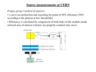
Diagnostics • THz Schottky diode detectors • from a dedicated dipole beamport • B22 beamline (FTIR) • Streak camera • Orbit data in dispersive BPMs 60-90GHz SBD 220-300GHz SBD TWIICE SOLEIL, 17th January 2014
B22 beamline (FTIR) CSR gain ~200,000 CSR gain ~1000 Courtesy G. Cinque CSR amplification factor for short pulse THz mode (above the bursting threshold) CSR gain > 1000 up to 100 cm–1 TWIICE SOLEIL, 17th January 2014
Characteristics of THz emission Instability thresholds and quadratic dependence with current in good agreement with theory: Shielded CSR theory: α1 > 0 From VFP simulations: From free-space CSR theory: Bane, Cai, Stupakov, PRST-AB 13, 104402 (2010) Wuestefeld et al., IPAC 2010, p. 2504 (2010) Cai, IPAC 2011, p. 3774, (2011) Ries et al., IPAC 2012, p. 3030 (2012) TWIICE SOLEIL, 17th January 2014
Measurement of time structure of THz pulses Positive alpha α1 = +1×10⁻⁵ VRF = 3.4MV fs0 = 675Hz Ibunch = 8.5µA α1 = +1×10⁻⁵ VRF = 3.4MV fs0 = 675Hz Ibunch = 21.9µA α1 = +1×10⁻⁵ VRF = 3.4MV fs0 = 675Hz Ibunch = 30.8µA α1 = +1×10⁻⁵ VRF = 3.4MV fs0 = 675Hz Ibunch = 37.7µA α1 = +1×10⁻⁵ VRF = 3.4MV fs0 = 675Hz Ibunch = 45.0µA α1 = +1×10⁻⁵ VRF = 3.4MV fs0 = 675Hz Ibunch = 63.0µA α1 = +1×10⁻⁵ VRF = 3.4MV fs0 = 675Hz Ibunch = 81.1µA α1 = +1×10⁻⁵ VRF = 3.4MV fs0 = 675Hz Ibunch = 97.2µA Instability threshold TWIICE SOLEIL, 17th January 2014
Measurement of time structure of THz pulses Negative alpha α1 = -1×10⁻⁵ VRF = 3.4MV fs0 = 675Hz Ibunch= 8.3µA α1 = -1×10⁻⁵ VRF = 3.4MV fs0 = 675Hz Ibunch = 18.4µA α1 = -1×10⁻⁵ VRF = 3.4MV fs0 = 675Hz Ibunch = 33.0µA α1 = -1×10⁻⁵ VRF = 3.4MV fs0 = 675Hz Ibunch = 40.8µA α1 = -1×10⁻⁵ VRF = 3.4MV fs0 = 675Hz Ibunch = 49.3µA α1 = -1×10⁻⁵ VRF = 3.4MV fs0 = 675Hz Ibunch = 55.5µA α1 = -1×10⁻⁵ VRF = 3.4MV fs0 = 675Hz Ibunch = 60.7µA Bursting threshold Instability threshold TWIICE SOLEIL, 17th January 2014
Measurement of time structure of THz pulses Many different operating conditions were investigated varying alpha, voltage, fill pattern, detector BW, showing a dauntingly rich phenomenology = -0.6 10–5 = 0.6 10–5 VRF = 3.4 MV VRF = 4 MV VRF = 4 MV VRF = 3.4 MV = -1.410–5 = 1.4 10–5 VRF = 4 MV VRF = 2.2 MV VRF = 4 MV VRF = 2.2 MV
Equation of motion (I) Particles move in the focussing fields of quads (transverse motion) cavities (longitudinal motion) The one turn map for each single particle reads Transverse Longitudinal Includes RF nonlinear potential, chromaticity (and simplecticity) TWIICE SOLEIL, 17th January 2014
Equation of motion (II) Radiation damping and diffusion for electrons Transverse Longitudinal These terms guarantee that when tracking a distribution of macroparticles the equilibrium distribution is has the correct equilibrium emittances, beam sizes, divergences, bunch length and energy spread. TWIICE SOLEIL, 17th January 2014
Equation of motion (III) Wakefields are generated via the interaction of the beam with the vacuum pipe, by synchrotron radiation and by direct space charge Transverse Longitudinal The effect of the wakefield on the single particle motion is lumped in a kick added to the one turn map (both transverse and longitudinal) The kick is computed binning the longitudinal distribution of the electrons and computing W and W|| from analytical formula or numerical codes TWIICE SOLEIL, 17th January 2014
Wakefields implemented - CSR impedance with shielding
Simulating the THz pulses as detected by the SBD • The code is capable of • reproducing the THz pulse as detected by the SBD within the BW of the detector • producing the spectrogrammes (FT of the time signals) vs current as measured • It has been used to replicate • bunch lengthening curve • centre of charge shift • THz spectrum • mainly by using • CSR wake • BBR impedance fit (single resonance, R,L,C) • purely inductive impedance L TWIICE SOLEIL, 17th January 2014
α1=-1.0x10⁻⁵ / VRF = 3.4 MV The CSR wake was defined using the machine parameter for bending radius and height of the pipe – no fit simulations measurements • CSR only • generates a fine structure in the THz spectrum • missing transition with current in THz spectrum • bunch lengthening off TWIICE SOLEIL, 17th January 2014
α1=-1.0x10⁻⁵ / VRF = 3.4 MV Adding a BBI with parameter fitted to achieve the best agreement with the data: e.g. Q = 2; r = 310 GHz; Rs = 41 kOhm simulations measurements • CSR + BBI • generates a fine structure in the THz spectrum • transition with current in THz spectrum present albeit at higher current • bunch lengthening well reproduced TWIICE SOLEIL, 17th January 2014
α1=-1.0x10⁻⁵ / VRF = 3.4MV Adding a BBI with parameter fitted to achieve the best agreement with the data: e.g. Q = 1; r = 260 GHz; Rs = 36 kOhm simulations measurements • CSR + BBI • generates a fine structure in the THz spectrum • transition with current in THz spectrum present albeit at higher current • bunch lengthening well reproduced TWIICE SOLEIL, 17th January 2014
Same CSR+BBI, different machine conditions simulations Measurements = -1.410–5 V = 4 MV simulations Measurements = 1.010–5 V = 3.4 MV
Time signals from SBD Measurements = -1.010–5 V = 3.4 MV Simulations spectrum of SBD signal 2*s= 2 * 677.94 Hz Bunch current = 50 Amp nturrn = 100,000 / analysed last 80,000 turns
Longitudinal dynamics above threshold for negative alpha Simulations = -1.010–5 V = 3.4 MV 50 uA - bursting No evidence of microbunching – bursting entirely described by the form factor current = 50 microAmps in conditions of stable bursting
Time signals from SBD and orbit data Simulations = -1.010–5 V = 3.4 MV spectrum of SBD signal s= 677.94 Hz FFT of horizontal motion H Orbit PSD (α = -4.5×10⁻⁶) above bursting H Orbit PSD (α = -1.0×10⁻⁵) below bursting
Conclusions and ongoing work • Numerical tracking seems to be capable of reproducing the phenomenology of the single bunch dynamics above threshold and the THz emission • Qualitative agreement even with a simple BBR resonator but the results are very sensitive to the details of the impedance model used • Investigation of dynamics above the bursting threshold shows • numerical evidence that bursting with negative alpha is not due to microbunching • numerical evidence (TBC) that different bursting modes (and transition between bursting mode within the same machine conditions) might be generated by different wakefields becoming unstable • Code development: real lattice tracking, more macroparticles, …. TWIICE SOLEIL, 17th January 2014