Download
1 / 21
220 likes | 482 Views
Report from Mini-Workshop: Simulation of Power Dissipation and Heating from Wake Losses in Accelerator Structures. Guenther Rehm Diamond Light Source. Convert V/ pC to W. For all bunches filled, more if shorter fill, n ot taking into account c oherent effects. Motivation.

E N D
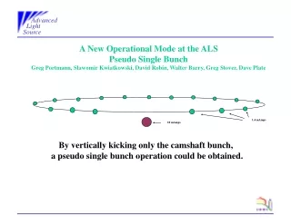
Report from Mini-Workshop:Simulation of Power Dissipation and Heating from Wake Losses in Accelerator Structures Guenther Rehm Diamond Light Source
Convert V/pC to W For all bunches filled, more if shorter fill, not taking into account coherent effects
Motivation • Simulations of wake losses using various 3D EM codes are used to calculate wake loss factor or wake impedance. • We now know what power is lost from the beam, but where is it dissipated? • How much of the power is radiated back into the beam pipe or transmitted into external ports (where present) and how much is actually being dissipated in the structure, and where? • (What is the impact of the dissipated power in terms of deformation, stresses or potential damage?)
Participants • Workshop held at DLS on 30 January 2013 • Thomas Guenzel, Ubaldo Iriso (ALBA) • Fritz Caspers, Elias Metral (CERN) • Dirk Lipka (DESY) • Alun Morgan, Morten Jensen, Richard Fielder, Shivaji Pande, Riccardo Bartolini, Guenther Rehm, Ian Martin, Ed Rial (DLS) • Sara Casalbuoni, Robert Voutta, Benjamin Kehrer and Stefan Gerstl (KIT) • Alexei Blednykh(NSLS-II via EVO) • Alexey Lyapin (RHUL) • Alexander Novokhatski (SLAC) • Ryutaro Nagaoka (Soleil) • Jim Clarke, Tom Bradshaw (STFC)
Relevance for low emittance rings? • Low emittance rings often end up with small vacuum chamber dimensions to facilitate magnets, higher cut off, trapped mode freq • Short bunch lengths (3 mm and less) create rich excitation up to many 10 GHz • At the same time, high bunch charge/stored current turn each mV/pC into about one W • Diagnostics components are often at risk as they are designed to couple to the beam
This short report will: • Concentrate on the methods applied by the presenters / their groups • Only mention the specific components investigated, without going into detail • Conclude with a proposal how to get most reliable results • Slides of all contributions http://tinyurl.com/wakeloss
PEP-II / A. Novokhatski et alMAFIA, NOVO, OMEGA3P / BPMs, bellows, valves, flanges, ante-chambers, collimators • TD and Eigenmode simulations • Identify regions at danger from modes • Noted that large amounts of energy can travel through beam pipe, but not quantified • Many components damaged in operation despite good design and lots of simulation effort • Change design to avoid source of wake losses where possible • Adding ceramic tiles to localise losses • Add water cooling to almost everything
LHC / E. Metral et alAnalytical, CST PS / RF fingers, kickers, various chambers • Broadband impedance • Narrowband impedance • Bunch profile / spectrumis important!
LHC / E. Metral et alAnalytical, CST PS / RF fingers, kickers, various chambers • Timedomainwakefield simulation to get loss factor • Compute wake impedance from long range wake potential • Estimate power in individual modes from impedance spectrum • Eigenmode simulation to assess structure of strong modes • Damp resonances by design change, add ferrites • No information on dissipated power distribution sought
KIT / S. Casalbuoni et alAnalytical, CST PS / Cold Liner • Analytical investigation of step transitions, tapers, surface roughness, resistive wall effect • Analytical and CST PS simulation of coupling slots found negligible loss • CST PS of whole structure found no long range wake fields • Resistive wall losses dominate in this case • Not clear where power lost at step transitions ends up
DESY / D. LipkaCST PS / Current Transformers • TD wakefield simulation to get loss factor • Eigenmodesimulation to get field distribution of losses from wall currents, dielectric losses • Pickone mode associated with highest peak of wake impedance • Thermal simulation using all power distributed according to mode to get temperature distribution • Works well for simple structures with one dominant mode • Quick simulation: only short range wake and a few eigenmodes • Cannot be applied where many modes exist • No account for power lost through beam pipes or ports
NSLS-II / A. Blednykh et alGdfidL / BPM, Stripline, Bellows • TD wakefield simulation to get loss factor • Compute wake impedance from long range wake potential • Evaluate impedance for various fill patterns • Eigenmode simulations to identify location of modes, modify design to suppress • For thermal simulation assign all power to most ‘fragile’ component • Classic approach, reasonable for designs in early stage • Quick simulation: only short range wake and a few eigenmodes • Difficult to be applied where many modes exist • No account for power lost through beam pipes or ports
Soleil / R. Nagaoka et alAnalytical, GdfidL / Flanges, BPMs, tapers, striplines, coatings • TD wake loss simulation • Take several snapshots of H field and calculate wall current losses, average • Vary conductivity of components to partition total power • Quick, requires only one TD simulation • Time average of a few slices is not necessarily a good proxy • Material losses not part of TD simulation H//: Tangential magnetic field k : Conductivity d : Skin depth at the resonant frequency
DLS/ A. Morgan et alCST PS / Striplines, BPMs • TD long range wake potential • Record port (also beam pipe) signals on many modes • Repeat while varying conductivity of components • Energy deposited equals energy lost less energy emitted • Using wake impedance and spectra of port signals this account can be done for each frequency • Takes into account emission into ports • Takes into account material losses during TD simulation • Energy conservation not always achieved in current simulation • Requires many long range simulations • Total disturbance of single material change is not always small
Example of Energy Accounting Signal 2 Signal 1 Output Input
ALBA / T. GuenzelGdfidL / Kicker Stripline • TD wakefield simulation for loss factor • Calculate Eigenmodes up to TM cutoff of beam pipe, get shunt impedance for each • Modify component resistance piece by piece to get ‘component’ Q value • Use each mode as starting condition for TD ‘ringdown’ to determine Qextfrom port signals • Evaluate power with spectrum of various fill patterns • Take component power as volumetric heat input to thermal FEA
ALBA / T. GuenzelGdfidL / Kicker Stripline • Should take into account all modes and partition power accordingly to modes / components • Requires many simulations (one TD ringdown per mode) • Eigenmode solver can produce ‘unreal trapped’ modes due to lossless boundary conditions (new version should support lossy boundary!) • Uncertainty from account of power lost through ports. TD does not simulate material losses, so port signals likely overestimated (maybe lossy boundaries in Eigenmode simulation are also taken into account for Q calculation?)
How power dissipation could be calculated straight forward None of the existing codes can do this at the moment (to my knowledge): • TD simulation of long range wake potential • Allow excitation with train of bunches to simulate coherent case • Integrate over whole simulation time: • Energy dissipated in each simulation cell due to ohmic losses (including skin effect!), or complex permittivity and permeability • Energy lost through ports (integrate Poynting vector over open boundaries)
Conclusions • Integrated calculation of dissipated power distribution from wake losses not available at the moment. • Post processing analysis complicated and time consuming, often needs many simulation runs. • None of the demonstrated methods is fully consistent, often good only as indication. • Please appeal to code developers to integrate changes or propose alternative!
Acknowledgements • Thanks to the authors and collaborators of all the workshop contributions • Thank you for your attention