Download
1 / 43
430 likes | 551 Views
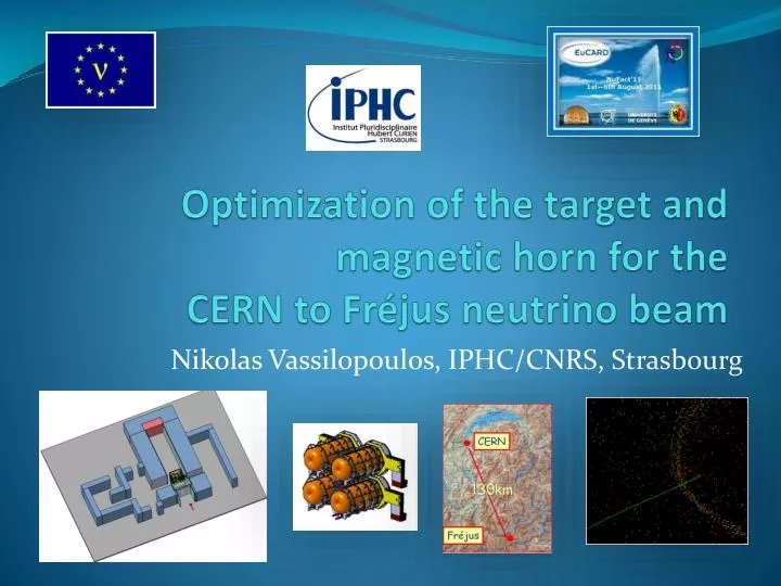
Optimization of the target and magnetic horn for the CERN to Fréjus neutrino beam . Nikolas Vassilopoulos, IPHC/CNRS, Strasbourg . Talk layout. Target Studies Horn shape & SuperBeam Geometrical Optimization Horn Thermo-mechanical Studies Energy Deposition, Irradiation and Safety Studies .

E N D
Optimization of the target and magnetic horn for the CERN to Fréjus neutrino beam Nikolas Vassilopoulos, IPHC/CNRS, Strasbourg
Talk layout • Target Studies • Horn shape & SuperBeam Geometrical Optimization • Horn Thermo-mechanical Studies • Energy Deposition, Irradiation and Safety Studies SPL SuperBeam Studies @ NUFACT11
Proton Beam and Target/Horn Station • Eb = 4.5 GeV • Beam Power = 4MW -> 4x1-1.3MW • Repetition Rate = 50Hz -> 12.5Hz • Protons per pulse = 1.1 x 10¹⁴ • Beam pulse length = 0.6ms • 4-horn/target system in order to accommodate the 4MW • power @ 1-1.3MW, repetition rate @ 12.5Hz for each target Ilias Efthymiopoulos/CERN SPL SuperBeam Studies @ NUFACT11
beam window 0.25 mm thick beryllium window Circumferentially water cooled (assumes 2000 W/m2K) Max temp ~ 180 °C Max stress ~ 50 MPa (109oC and 39 MPa using He cooling) feasible Matt Rooney SPL SuperBeam Studies @ NUFACT11
Important Issues for the engineering of the target • Heat Removal • Beam ≈ 60 – 120kW depending on Target Material/configuration • Thermal/mechanical stresses • long lived “quasi-static” stresses that generated by temperature variations within the target • inertial dynamic stress waves that are generated by the pulsed nature of the beam • Cooling • water • helium • peripheral vs transversal cooling • Neutron Production – heat load/damage of horn • Safety • Radiation resistance • Reliability • Pion yield Chris Densham et al. @ RAL SPL SuperBeam Studies @ NUFACT11
from Liquid Targets to Static Packed one EUROnu-WP2-note-11-01 favourable baseline for WP2 SPL SuperBeam Studies @ NUFACT11
favourable methods SPL SuperBeam Studies @ NUFACT11
with peripheral cooling Ottone Caretta/RAL ruled out SPL SuperBeam Studies @ NUFACT11
Packed bed Target • Why packed bed target with transversal cooling is the baseline option ? • Large surface area for heat transfer • Coolant able to access areas with highest energy deposition • Minimal stresses • Potential heat removal rates at the hundreds of kW level • Pressurised cooling gas required at high power levels • Bulk density lower than solid density • From a thermal and engineering point of view seems a reasonable concept where stress levels in a traditional solid target design look concerningly high SPL SuperBeam Studies @ NUFACT11
Tristan Davenne/RAL SPL SuperBeam Studies @ NUFACT11
Tristan Davenne/RAL SPL SuperBeam Studies @ NUFACT11
Stresses for the Packed bed target EUROnu example, 24mm diameter cannister packed with 3mm Ti6Al4V spheres • Quasi thermal and Inertial dynamic components ideally spill time > oscillation period Tristan Davenne/RAL SPL SuperBeam Studies @ NUFACT11
Alternative solution: pencil “closed” Be Solid target Mike Fitton, Peter Loveridge/RAL • Pencil like Geometry merits further investigation • Steady-state thermal stress within acceptable range • Shorter conduction path to coolant • Pressurized helium cooling appears feasible • Off centre beam effects could be problematic? • Needs further thermo-mechanical studies SPL SuperBeam Studies @ NUFACT11
Horn Studies details in WP2 notes @ http://www.euronu.org/ evolution of the horn shape after many studies: • triangle shape (van der Meer) with target inside the horn : in general best configuration for low energy beam • triangle with target integrated to the inner conductor : very good physics results but high energy deposition and stresses on the conductors • forward-closed shape with target integrated to the inner conductor : best physics results, best rejection of wrong sign mesons but high energy deposition and stresses • forward-closed shape with no-integrated target: best compromise between physics and reliability • 4-horn/target system to accommodate the MW power scale SPL SuperBeam Studies @ NUFACT11
Horn Shape and SuperBeam geometrical Optimization • minimize λ, the δcp-averaged 99%CL sensitivity limit on sin22θ13 • broad scan, then fix & restrict parameters then re-iterate for best horn parameters & SuperBeam geometry A. Longhin/CEA SPL SuperBeam Studies @ NUFACT11
Horn Stress Studies • horn structure • Al 6061 T6 alloy; good trade off between mechanical strength, resistance to corrosion and electrical conductivity and cost • horn thickness has to be as small as possible for the best physics performance and to limit energy deposition from secondary particles but thick enough to sustain dynamic stress from the pulsed currents. • horn stress and deformation • magnetic pressure and thermal dilatation • COMSOL, ANSYS software • cooling • water SPL SuperBeam Studies @ NUFACT11
EUROnu scenario for 4-horn system SPL SuperBeam Studies @ NUFACT11
B. Lepers/IPHC, P. Cupial , L. Lacny/Cracow Univ. of Tech. Stress Analysis for the SPL SuperBeam Horn I • Thermo-mechanical stresses: • secondary particles energy deposition and joule losses • T=60ms, τ0=100μs, Irms=10.1kA, f=5kHz (worst scenario, 1horn failed) • TAl =600C, {hcorner , hinner, hhorn/out }= {6.5, 3.8, 0.1} kW/(m2K) • Smax = 62MPa B. Lepers/IPHC SPL SuperBeam Studies @ NUFACT11
Stress Analysis II • Combined analysis of Thermo-mechanical and magnetic pressure induced stresses: • significant stress or the inner conductor especially, for the upstream corner and downstream plate inner part • high stress at inner conductor welded junctions • thermal dilatation contributes to longitudinal stress; displacement is low due to the magnetic pulse • maximum displacement at downstream plate • horn lifetime estimation: results have to be compared with fatigue strength data • more water-jet cooling might be applied B. Lepers/IPHC SPL SuperBeam Studies @ NUFACT11 displacement and stress time evolution , peak magnetic field each T=80ms (4-horns)
Cooling Studies B. Lepers, V. Zeter, IPHC power distribution on Al conductor • planar and/or elliptical water jets • flow rate between 60-120l/min • h cooling coefficient 1-7 kW/(m2K) • EUROnu-Note-10-06 • design for 600C uniform horn temperature: • {hcorner , hinner , houter/horn }= {6.5, 3.8, 1} kW/(m2K)/longitudinal repartition of the jets follows the energy density deposition • 30 jets/horn, 5 systems of 6-jets longitudinally distributed every 600 SPL SuperBeam Studies @ NUFACT11
Power Supply Studies P. Poussot, J. Wurtz/IPHC horn focusing plateau • Energy recovery with an inductance L, switch and capacitor: • good energy recuperation 60% • best solution in terms of feasibility and cost energy recovery SPL SuperBeam Studies @ NUFACT11
for Experimental Hall (Target/Horns, DT, Beam Dump), Safety Gallery, Maintenance Room, Waste Area SPL SuperBeam Studies @ NUFACT11
Safety II beam dump Design includes: • Proton Driver line • Experimental Hall • MW Target Station • Decay Tunnel • Beam Dump • Maintenance Room • Service Gallery • Power supply • Cooling system • Air-Ventilation system • Waste Area shielding spare area target/horn station decay tunnel (25 m) hot cell horn power supply and electronics gallery beam SPL SuperBeam Studies @ NUFACT11
rock: molasse @ CERN Energy deposition and Activation StudiesFLUKA MC + FLAIR concrete ACTIVITY density in Bq/cm3 Fe shields, vessels graphite beam dump He vessels: T&H : L=8m, tFe =10cm , tconcrete=5.7cm DT : L =25m, tFe =1.6cm , tconcrete=5.6cm BD : L =8m, tFe =10-40cm , tconcrete=5.7cm molasse concrete POWER density in kW/cm3 molasse concrete Ptot =3.4MW • energy is confined from concrete thickness • minimum activation of molasse rock • minimum/none effective dose to humans in other galleries • detailed tables of the radionuclides • water contamination from tritium is well kept under safety levels Eric Baussan, N. Vassilopoulos/IPHC SPL SuperBeam Studies @ NUFACT11
Energy Deposition in Beam Dump vessel • concrete: • t = 5.6m • L = 8.4m • He vessel + iron plates, water cooled • tFe = 10-40cm • LFe= 4m • upstream shield (iron plates), water cooled • tFe = 40cm • LFe = 1m • Graphite beam dump: • L = 3.2m, W = 4m, H = 4m • P = 530kW • downstream iron shield (iron plates), water cooled: • LFe = 40cm, WFe = 4m, HFe = 4m • PFe = 10.3kW • outer iron shields (iron plates), water cooled • L Fe= 2m, WFe = 4.8m, HFe = 4.8m • PFe = 1.1kW 530kW SPL SuperBeam Studies @ NUFACT11
molasse @ CERN Activation in molasse(full 4horn simulation, medium stats: 106 protons, 20% error) concrete study set up: • packed Ti target, 65%dTi • 4MW beam, 4horns, 200days of irradiation • minimum activation leads to minimum water contamination • concrete thickness determines the activation of the molasse • results: • of all the radionuclide's created 22 Na and tritium could represent a hazard by contaminating the ground water. Limits in activity after 1y=200days of beam: Activity distribution SPL SuperBeam Studies @ NUFACT11
Target Activity at Storage Area Eric Baussan, N. Vassilopoulos/IPHC study set up: • packed Ti target, 65%dTi • 1.3MW beam, 200days of irradiation • no other activation at storage area SPL SuperBeam Studies @ NUFACT11
Dose Rates for target/horn at Storage/Service Area, I • radiation limits as in CNGS notes: • rates (e.g.): • at 60cm distance from the outer conductor (calculation of the rates using 20cmx20cmx20cm mesh binning through out the layout -> choose a slice of x-axis with 20cm thickness and 60cm away ) z x SPL SuperBeam Studies @ NUFACT11
Dose Rates target/horn at Storage Area, II 1month 1year > 1 Sv/h > 50 mSv/h palette in mSv/h 100years 50years > 0.01 mSv/h • high effective dose rates for the target/horn system makes them inaccessible -> remote handling mandatory Eric Baussan, N. Vassilopoulos/IPHC SPL SuperBeam Studies @ NUFACT11
Conclusions • Horn with separated target baseline as result of dynamic and static stress analyses • 4-horn system to reduce the 4MW power effects • Horn shape defined as forward-closed due to best physics results and reliability issues • Packed-bed Target is preferable in multi-Watt beam environment due to minimum stresses and high heat rate removal due to transverse cooling among others • Stress analysis support the feasibility of the target/horn design. Furthermore the power supply design looks feasible as well • Minimum activation in molasse rock for current secondary beam layout • High dose rates in Storage Gallery -> remote handling for repairs mandatory • to be continued ... Thanks SPL SuperBeam Studies @ NUFACT11
pen like target: cooling looks feasible SPL SuperBeam Studies @ NUFACT11
considerations: SPL SuperBeam Studies @ NUFACT11
Horn shape and SuperBeam geometrical Optimization I studies by A. Longhin, EUROnu-WP2-10-04 • parameterise the horn and the other beam elements • as decay tunnel dimensions, etc... • parameters allowed to vary independently • minimize the δcp-averaged 99%CL sensitivity limit on sin22θ13 SPL SuperBeam Studies @ NUFACT11
Horn Shape and SuperBeam geometrical Optimization II fix & restrict parameters then re-iterate for best horn parameters & SuperBeam geometry SPL SuperBeam Studies @ NUFACT11
Physics Performance for different Targets I • Graphite Solid target, 2λI • Hg, 2λI • Integrated target, 2λI • excellent performance of packed bed Ti, d= 74%dTi CERN to Frejus/MEMPHYS neutrino beam any density reduction of packed could be recuperated increasing the horn current by 50, 100 kA SPL SuperBeam Studies @ NUFACT11
Physics Performance for different Targets II • Graphite Solid target, 2λI • Hg, 2λI • Integrated target, 2λI • excellent performance of packed bed Ti, d= 77%dTi CERN to Frejus/MEMPHYS neutrino beam any density reduction of packed could be recuperated increasing the horn current by 50, 100 kA SPL SuperBeam Studies @ NUFACT11
Energy Deposition from secondary particles on Horn, 1.3MW, Ti packed bed targetFLUKA MC+FLAIR target Ti=65%dTi , RTi=1.5cm 36kW, t=30mm 8.6kW, t=35mm 1.7kW 2.5kW 2.4kW 1.3kW 9.5kW radial profile of power density kW/cm3 Ptg = 105kW Ph = 62kW SPL SuperBeam Studies @ NUFACT11
Energy Deposition on horns # 2,4, active horn is #1 • 1.3MW beam, 350kA, graphite target shown upstream plates Etoth= 14.4kW 2nd 1st 1st 3rd 4th Etoth= 0.8kW 2nd or 4th SPL SuperBeam Studies @ NUFACT11
Energy deposition on SuperBeam Elements Power density distributions in kW/cm3 concrete P=530kW P=3.4MW Gr beam dump SPL SuperBeam Studies @ NUFACT11
<doses> in longitudinal plane along beam axis after 200d of irradiation 1day 6months Beam Dump Beam Dump Horns Horns DT area DT area palette in mSv/h 1year 10years Beam Dump Beam Dump Horns Horns DT area DT area • high dose rates along SuperBeam layout->remote handling mandatory for any part of the 4-horn system in target/horn station SPL SuperBeam Studies @ NUFACT11