Download
1 / 22
220 likes | 225 Views
LARP Collimation – Engineering & Analysis. Adapting the NLC Consumable Collimator to LHC Phase II Secondary Collimation. BEAM 2. BEAM 1. LARP Collimation – Engineering & Analysis. Overview Review NLC consumable collimator Compare NLC & LHC requirements

E N D
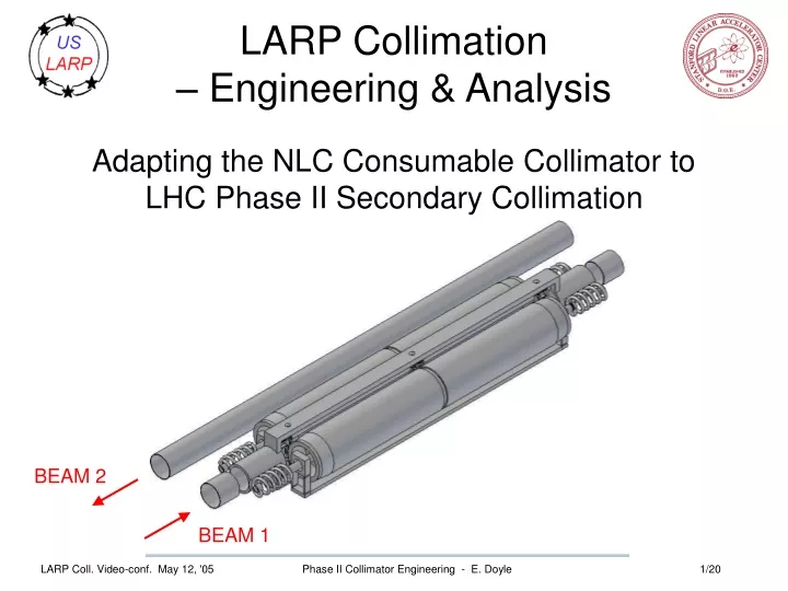
LARP Collimation– Engineering & Analysis Adapting the NLC Consumable Collimator to LHC Phase II Secondary Collimation BEAM 2 BEAM 1 Phase II Collimator Engineering - E. Doyle
LARP Collimation – Engineering & Analysis • Overview • Review NLC consumable collimator • Compare NLC & LHC requirements • Conceptual design: NLC collimator as adapted to LHC • Thermal performance of candidate materials • Unresolved issues Phase II Collimator Engineering - E. Doyle
NLC Consumable Collimator BPMs (not shown) at inlet & outlet Aperture is sole internal degree of freedom. Movers align collimator to beam as sensed by BPMs Phase II Collimator Engineering - E. Doyle
NLC Consumable Collimator Heat dissipated by radiation. DT = 42C @ 10W/jaw Rigid datum structure aligned to beam by BPMs Aperture control mechanism: Thermal effects limited to small region Phase II Collimator Engineering - E. Doyle
NLC Test Unit Cutaway Aperture support one end of rotor only Dual ball bearings preloaded for tilt-stability Phase II Collimator Engineering - E. Doyle
NLC Aperture-control MechanismLocated at one end of rotor only.Tilt–stability not well controlled in test unit. Phase II Collimator Engineering - E. Doyle
NLC Aperture-Defining GeometryOne independent variable (stop roller spacing) defines aperture. s = stop roller spacing Phase II Collimator Engineering - E. Doyle
Major Differences - NLC & LHC Specs Phase II Collimator Engineering - E. Doyle
LHC Collimator Mechanism ConceptBasic NLC design morphed to fit LHC constraints Jaws hidden to show structure • 1.2m long jaws, 150mm diameter • Helical coolant supply tubes flex, allow one rev of jaw • Aperture supported a both ends for stability, tilt adjustment • Also shown: aperture support at jaw center • thermal deflection away from beam • no tilt control Phase II Collimator Engineering - E. Doyle
Thermal Distortion ANSYS Simulations 10 s apertures beam • 150mm OD, 25mm wall, 1.2m long • Simply supported • FLUKA heat generation for 10x10x24 rectangular grid mapped to similar area of cylinder • Steady state: 1hr beam lifetime • Transient:10 sec @ 12 min beam lifetime • I.D. water-cooled 20C, h=11880 W/m^2/ • Various materials: Al, 2219 Al, Be+Cu, Cu, Invar, Inconel • Ti, W rejected based on 2-D analysis • Variations • limit cooling to 45o arc • solid cylinder • jaw cut in two shorter pieces Cu, 61C support dx=221 um support Phase II Collimator Engineering - E. Doyle
360o cooling of I.D. 45o cooling arc Note transverse gradient causes bending Note axial gradient 61C 89C Note more swelling than bending support dx=221 mm Spec: 25mm dx=79 mm 64% less distortion support Phase II Collimator Engineering - E. Doyle
Material Comparison for SS & Transient Thermal DeflectionGreen: meets alternative spec of 50um (SS) and 200um (transient). • Notes: • BeCu is a made-up alloy with 6% Cu. We believe it could be made if warranted • 2219 Al is an alloy containing 6% Cu • Cu/Be is a bimetallic jaw consisting of a 5mm Cu outer layer and a 20mm Be inner layer • Cu – 5 mm is a thin walled Cu jaw • Super Invar loses its low CTE above 200C, so the 152um deflection is not valid Phase II Collimator Engineering - E. Doyle
Jaw Materials - discussion • Only graphite meets the 25um deflection spec for both operating cases. • Be-containing jaws meet the spec for the SS case but not for the transient. • Be is unacceptable for environmental/safety reasons. • Al benefits from the reduced (45o) cooling arc. • nearly meets the spec for SS condition • Excessive deflection for the transient • What next? • Divide jaw in shorter sections • Use center-of-jaw aperture stops - jaw deflects away from the beam • Revisit materials not modeled in 3-D: W & Ti Phase II Collimator Engineering - E. Doyle
Effect of shortened jaws, dense material, carbon pre-radiator • Notes: • Aperture transition from 10s to 7s • 7s cases based on CERN ray files for interactions in TCPV • pre-radiator – Phase I carbon collimator concentrates energy deposition toward front of Phase II jaw. Phase II Collimator Engineering - E. Doyle
Shortened jaws/dense material - discussion • Dividing jaws beneficial • Short front jaws more swelling than bending • Cu jaws nearly meet relaxed specs • W jaws look good, but: • temperatures and power densities very high (cooling system) • deflections much greater if referred to jaw centerline • What next? • Increase cooling arc in W jaws • Simulate single 48cm W jaw • Calculate cooling system loads Phase II Collimator Engineering - E. Doyle
Conceptual design - coolant channels Limited cooling arc: free wheeling distributor – orientation controlled by gravity – directs flow to beam-side axial channels regardless of jaw angular orientation. Far side not cooled, reducing DT and thermal distortion. 360o cooling by means of a helical channel. Lowers peak temperatures but, by cooling back side of jaw, increases net DT through the jaw, and therefore thermal distortion. Could use axial channels. Phase II Collimator Engineering - E. Doyle
Conceptual design - Stop Roller Details Ball nut (turned by actuator outside vacuum chamber). Ball screw (stationary) Thrust bearing Hole for beam passage As shown in current model: aperture range limited to ~ 10mm. This can be improved but this mechanism will not be able to produce the full 60mm aperture. Auxiliary jaw retracting mechanism needed. Also note vulnerability of mechanism to beam-induced heating. Phase II Collimator Engineering - E. Doyle
Beam’s Eye View of Aperture Mechanism Jaw retracted, aperture ~60mm Phase II Collimator Engineering - E. Doyle
Geometrical limits due to 150mm rotor, 224 mm Beam Axis Spacing 30mm jaw travel (in red) causes jaw to intersect adjacent beam pipe. No space for vacuum chamber wall. Resolution: 1) smaller jaw diameter 2) vacuum envelope encloses adjacent beam pipe 3) less jaw motion 4) reduce diameter of adjacent beam pipe. Phase II Collimator Engineering - E. Doyle
Alternate Stop-Roller Design Phase II Collimator Engineering - E. Doyle
Status of Phase II LHC Collimator Concept • Deflection spec will be very hard to meet • Relax deflection spec • Allow use of Be • Reduce jaw length • Aperture stop mechanisms vulnerable to beam heating/damage • Relocate ball screw outside beam path – like NLC (jaw ends only) • Stop rollers unavoidably within region of beam pipe • Combine NLC rotary jaws with LHC positioning mechanism • Space limitations prevent 60mm max aperture with 150mm o.d. jaws • Reduce jaw diameter • Will likely increase deflection • Adversely affects aperture stop mechanism • Reduce opposing beam pipe diameter • Include a pass-through for the opposing beam in the collimator vacuum chamber • Reduce the maximum required aperture Phase II Collimator Engineering - E. Doyle
Status of Phase II LHC Collimator Concept - continued • Cooling system loading is problematic for dense jaw materials • Other engineering issues • Jaws must fully retract in power-off condition • Spring load jaws outward. Inward-forcing springs (necessary in any case) sized to overcome outward-forcing springs and grounded on solenoid or pneumatic device which gives way when power is off. • Design of flexible coolant supply tubes • Manufacturability of jaws (material dependent) • How to apply heat loading for testing • Rotor indexing mechanism Phase II Collimator Engineering - E. Doyle