Download
1 / 27
270 likes | 484 Views
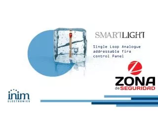
US1000 Single Loop Controller. Product Training. Process automation at its best. US1000 Overview. Universal Isolated Inputs and Outputs Thermocouple, RTD, mV or VDC inputs. ON/OFF, voltage pulse or 4-20mADC outputs. Optional position proportioning control using a Form C relay.

E N D
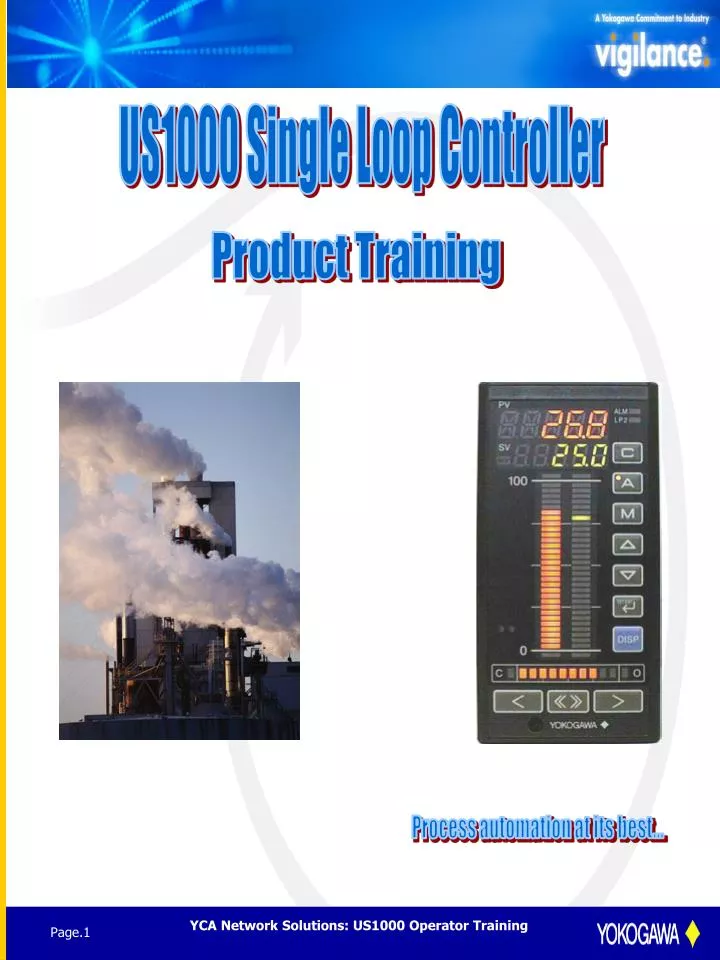
US1000 Single Loop Controller Product Training Process automation at its best...
US1000 Overview • Universal Isolated Inputs and Outputs • Thermocouple, RTD, mV or VDC inputs. • ON/OFF, voltage pulse or 4-20mADC outputs. • Optional position proportioning control using a Form C relay. • Multiple Discrete Inputs and Outputs • Up to 7 contact inputs. • Up to 7 contact outputs • Relay and solid state outputs (same as the GREEN Series). • Optional RS485 Communication • GREEN series PC-Link AND Modbus RTU communication. • Up to 9600bps using Modbus. • Up to 38.4Kbps using PC-Link • Power Supply for Two-wire Transmitters • Standard US1000 has 25.5VDC supply for one transmitter. • Enhanced version provides DC power for two transmitters. • Universal AC Power Supply • Rated at 100 to 240VAC. • Same power supply for 110VAC or 220VAC operation. • Agency Approvals • FM and CSA Non-incendive approval for Class 1 Div. 2 Groups A,B,C & D. • CE Mark required for installation in Europe. • Enclosure Size • Shallow depth at 149 mm. • Standard DIN 72x144 mm front panel. • Waterproof and Dust-proof Front Panel • IP65 rated (equivalent to NEMA 4) • Windows-based Configuration Tool • LL1100 and LL1200 software packages. • True “drop-and-drag” format. • Function blocks can be easily linked without using D-register numbers (as in GREEN series). • Light Loader Interface • RS485 connection with /A10 option.
Suffix Model Description Code Parameters Setting Tool LL1100 LL1200 Custom Computation Tool English Version -E10 US1000 Model Number Model Analog In Analog Out Relay Outputs TTL • Auxiliary input (1-5VDC or 0-10VDC) is used for remote set point or feed forward. • Enhanced options have two universal inputs. • RET (retransmission) is standard on all US1000’s (0-5VDC or 1-5VDC). • Standard version provides 24VDC power for ONE two-wire transmitter. • Enhanced version provides DC power for TWO transmitters. • Standard version has 2 contact inputs and 3 contact outputs (honest-to-goodness 1 amp relays). • Enhanced version has 7 contact inputs and 7 contact outputs (3 relays and 4 solid state outputs). • Optional /A10 RS485 Communication allows PC-link protocol or Modbus protocol, selectable in configuration. • Configuration Tools • LL1100 is used with all US1000 controllers. • LL1200 is required for custom computations. for the US1000-11 & US1000-21 only. • Each software package includes light loader module and cable. Contact In Heat/Cool Feedback Universal DC Power Auxiliary Outputs Pos. MV Alarms RET MV Description Suffix Single Loop Controller US1000 -00 Standard 1 1 1 1 1 2 3 Enhanced -11 2 1 2 2 1 7 3 2 4 -21 Enhanced with 2 1 1 2 1 1 7 3 1* 4 * Form C relay Position Proportional /A10 RS485 Communications
M3.5 screw terminals Screw for 149mm Depth Terminal cover Terminal Cover is one of the standard accessories. Rear Short Depth and IP65 Rated • Only 149 mm in depth (< 6 inches). 179 mm depth including terminal cover. • Easy field wiring using 3.5 mm screw terminals. • May be installed in a NEMA 4 enclosure. • Mounting brackets provided. • Less than 2 lbs. in weight. • IP65 front panel assembly. • Dust and water resistant. • IP6_: No ingress of dust. • IP_5: Protection from water spray. • Water nozzle diameter: 6.3 mm (0.25 in.) • Flow rate: 12.5 L/min (~3.3 gpm) • Distance from instrument: 3 meters (~10ft.) • IP65 rating applies for stand alone units only. Units mounted side-by-side can not comply.
Hazardous Areas Safety Approvals • Factory Mutual Research Company • Non-incendive for Class 1, Div. 2, Gps. A, B, C & D • NO additional cost… • Canadian Standards Association • Non-incendive C22.2-213 • Class 1, Div 2, Gps. A, B, C & D • NO additional cost… • Confomite Europeenne, European Union Safety Standards, EMC Standards. • CE Mark is required for installation in Europe. • NO additional cost...
Auto-tuning ends at 3rd peak. Being Auto-tuning SV PV PID control according to PID parameter obtained by auto-tuning. 100% 100% MV 0% Auto Tuning Function • Uses open loop response to calculate PID tuning parameters. • Controller automatically varies the MV from 0% to 100% to determine PV step response. • Auto tune is turned off after the third PV peak. • Yokogawa’s auto tune really works. • SUPER control (fuzzy logic) is available for unparalleled control stability during PV disturbances or set point (SV) changes.
PC or PLC MODBUS or PC-Link Max: 1200m Up to 31 controllers Optional /A10 PC or PLC Communication • US1000 controllers can communicate with a PC or PLC by Modbus or PC-Link communication protocol. • Modbus • RTU (binary) mode or ASCII mode • Selectable in the parameter setting mode or using LL1100/1200 Configuration Tool. • Modbus had become a de facto open architecture protocol. • PC-Link • Yokogawa’s proprietary protocol used with the GREEN series. • UT/UP controllers can be connected on the same data highway as the US1000. • Interface: RS485 • Two wire half duplex. • Four wire full duplex. • Transmission speed • Up to 9600bps using Modbus RTU or ASCII protocols. • Up to 38.4Kbps using PC-Link. • Up to 31 controllers can be connected to one serial port. • Distance is limited to 1200 meters (~4000 feet) without using repeaters.
Light Loader Programming Tool This tool includes a a software package, an infrared head and a cable. With this tool, the US1000 can be completely programmed, the program can be saved and archived for later use. The controller can also be tuned from the software. This is a must have.
User Friendly Front Panel Display 11 segment PV Display 5 digits ALM: Alarm Lamp LP2: Loop 2 Lamp Familiar bar graph indications of PV, SV & MV values. 11 segment PV display used to observe parameter data after pressing SET/ENT key for 3 seconds. Similar to GREEN Series. 11 segments allow full alphanumeric characters to be shown. Parameter name is shown in the PV display area. Value is shown the the SV/MV LED display. PV is indicated numerically at the top and in the left vertical bar. SV is shown numerically and as a single LED segment on the right vertical display. MV is shown numerically by pressing the DISP key and in the 10 segment horizontal display. C, A & M keys operate just like the YS100 series controllers. DISP key allows viewing of the second PV, SV and MV if a cascade or dual loop control strategy is used. LP2 lamp is illuminated while viewing this data. ALM lamp illuminates if any process alarm is active. < & > keys decrease and increase the MV (control output). Pressing the <<FAST>> key with the < & > speeds up the action. 7 segment SV & MV Display Cascade, Auto, Manual Keys with Lamps SV Bar Display 30 segments with over/under scale segment SV (Set Point) Increase/ Decrease Keys SET/ENT Key (to observe parameter data) PV Bar Display 30 segments with over/under scale segment DISP Key (to change display data) Light Loader Interface MV Bar Graph MV Increase/Decrease Keys External Dimensions: 72x144x150mm
Setpoint Adjustment Adjusting the setpoint is simple. • Make sure the auto key lamp is illuminated. If the cascade key is lit, then adjusting the setpoint manually will not be possible. • The setpoiont viewed either on the SV bar graph or the SV display at the top of the instrument. This display shows setpoint except when MV lamp is lit. • The setpoint is adjusted using the SV increase/decrease keys. Press and hold until the desired setpoint is obtained. SV Display Auto Key SV Bar Display SV (Set Point) Increase/ Decrease Keys PV Bar Display
Selecting Cascade Control Cascade control with the US1000 allows a setpoint signal from a remote source to set the setpoint automatically. Another common term for this is remote setpoint. This cascade signal can be analog or digital. Make sure the auto key lamp is illuminated. If it is not, press and hold the auto key until the lamp is lit. Press and hold the cascade key until the lamp is lit. Cascade Key
Manual Adjustment of Output At times, taking manual control of a valve or other control element may be necessary. The following will allow you to do this. • Make sure the manual key lamp is illuminated. If it is not, press and hold the manual key until the lamp is lit. • The output percentage is viewed either on the MV bar graph or the MV display at the top of the instrument. This display shows output only when MV lamp is lit, otherwise it is setpoint. • The output is adjusted using the MV increase/decrease keys. To adjust the output quickly, press and hold the fast key along with the increase /decrease key. MV Display when MV lamp is illuminated Manual Key MV Bar Graph MV Increase/Decrease Keys MV Fast Key
Accessing the Operating Parameters To make changes to the operating parameters or the set up parameters, use the SET/ENT key. • Press and hold the SET/ENT key down for 3 seconds. • To access operating parameters, any mode is OK. • To access Setup parameters, controller must be in manual. SET/ENT Key
Parameter Setting Using the Front Panel PV Display First Digit: Hierarchy of the Parameter Second to Fifth Digit: Parameter Name • Easy Configuration from the Front Panel • Full 11 segment LED for parameter name display. • Example above: • First PV digit shows hierarchy of the parameter menu. • Indicates the level of the menu being shown. • USM indicates control mode parameter. • 1 indicates Single Loop Control selection. • How to change parameters from the front panel: • Press the M key to force the US1000 operating mode into MANUAL. • Press the SET/ENT key for 3 seconds to enter the parameter setting area. • Press the SET/ENT key to the appropriate menu. • Use the SV keys to change any parameter value displayed. • Press the SET/ENT key to write to the parameter the new value. • Press the DISP key to maneuver to a higher level display. SV Display: Parameter Data
Simple PID Loop Control Various types of with 4-20mA Control Output Loop Control Select Controller Mode Input Type, Range, Burnout selection, etc. Define Universal Inputs Define Universal Inputs Output Type, Direct/reverse Action, Heat/Cool, etc. Define Control Outputs Alarm Function, Password, Set Other Parameters Communication, etc. PID parameters, Alarm set points, MV limit set points, etc. Set Operation parameters Set Operation parameters Operation Operation Parameter Set-Up Order
Waste Control w/ Zone PID Control Water Flow Sensor Gain/Bias + Feed Forward Compensation pH Sensor M Neutralizing solution Single Loop Control with Feed Forward Input • US1000-00 Control Example • pH control made easier… • PV input is the pH measurement. • Due to varying flow conditions, a flow meter is installed in the inlet pipe of the neutralization tank and used as the feed forward input signal. • Gain, bias and a first order lag can be applied to the flow input. • Feed forward is selected during configuration as the AIN 3 function. • Zone control may be used to install different PID values as the pH varies from SV. • RUN/STOP and AUTO/MAN selection using two discrete inputs. • High, high-high and low alarms are standard features. • Used for one reagent addition only, acid or caustic. • Can’t beat the low cost of ownership! • Need two reagents? Use the US1000-11 with custom computation capability. • Don’t forget the LL1100 for easy configuration with a PC.
100% cooling heating output output Outputs of controller output of PID 0% 50% 100% Controller Raw Materials Cooling Heating Output Output Steam Water Heating and Cooling Control (US1000-11) • Heating and cooling outputs are standard on the US1000-11. • Universal outputs for each output (relay, voltage pulse or DC current). • Process characteristics may differ tremendously in heating and cooling stages. • US1000 has two independent sets of PID tuning parameters, one for heating and one for cooling. • Same as GREEN series. • No additional cost.
Reactor Temp. Control 1 Jacket Temp. Raw Control 2 Materials Heat&Cool Steam Water Single Station Cascade Control with Two Universal InputsUT1000-11 • US1000-11 Control Example • Reactor control made simple. • Two thermocouple inputs, reactor and jacket temperatures. • Remote set point (CSV) or feed forward input is standard. • PV retransmission (RET) is standard. • Two control outputs for heating and cooling. • Both temperatures can be shown simultaneously. • Left bar graph: Reactor temperature. • Right bar graph: Jacket temperature. • Discrete inputs • RUN/STOP switching to the preset output (PMV). • Cascade OPEN/CLOSE switching. • CAS/AUTO/MAN switching. • Contact outputs • High and low alarms for both temperature inputs. • FAIL output. • Easy configuration from the front panel display. • PC configuration using the LL1100 or LL1200 software package.
Control Control 1 2 Raw Materials Cooler Cooling Materials Two Independent Controls with Universal InputsUS1000-11 • Another US1000-11 control example… • Two independent PID actions in one controller. • Universal inputs (T/C, RTD, mV or VDC) • Universal outputs (Relay, voltage pulse, DC current). • Both PV’s can be shown at once. • PV1 shown in the left bar graph. • PV2 shown in the right bar graph. • 25.5VDC power for two transmitters. • Seven contact inputs. • RUN/STOP switching to the preset output (PMV). • AUTO/MAN 1 & AUTO/MAN 2 selection. • Set point selection (SV) using 4 DI’s. • Seven contact outputs (3 relay and 4 solid state). • High and low alarms for both inputs. • FAIL output. • Easy front panel configuration. • PC configuration is simple using the LL1100. • Use the LL1200 for custom computation control.
SQ-root extraction Ratio SQ-root Control extraction Position feedback Direct /reverse rotation Valve position Position Proportioning Control • US1000-21 Control Example • Ratio Control using a motorized valve for flow control. • Wild flow is connected to the remote set point (CSV) input. • 25.5VDC power for two transmitters is provided. • Square root extraction can be applied to the D/P transmitter inputs. • Slidewire feedback input for indicating valve position as the MV. • Form C 3 amp relay for increasing/decreasing valve position. • 4 alarm outputs. • PV1 high & low alarms. • PV2 high & low alarms. • FAIL output • 7 discrete inputs • CASCADE/AUTO selection • AUTO/MANUAL switching • RUN/STOP switching • Set point selection (SV) using 4 DI’s.