Download
1 / 25
250 likes | 377 Views
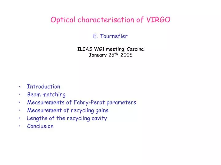
Optical characterisation of VIRGO E. Tournefier ILIAS WG1 meeting, Cascina January 25 th ,2005. Introduction Beam matching Measurements of Fabry-Perot parameters Measurement of recycling gains Lengths of the recycling cavity Conclusion. Radius of curvature. losses. Finesses F N , F W.

E N D
Optical characterisation of VIRGOE. TournefierILIAS WG1 meeting, CascinaJanuary 25th ,2005 • Introduction • Beam matching • Measurements of Fabry-Perot parameters • Measurement of recycling gains • Lengths of the recycling cavity • Conclusion
Radius of curvature losses Finesses FN, FW Recycling gains: Gcarrier, GSB modulation: Fmod, m l1 l0 l2 Input beam matching to the ITF Rrec losses Optical parameters of the ITF Contrast defect, CMRR And the lengthes: - Recycling length: lrec = l0+(l1 + l2)/2 - Asymmetry of the small Michelson: l = l1 - l2
Why are we interested in these measurements ? The mirrors parameters (reflectivity, losses, radius of curvature) have been measured in Lyon and are within the specifications. => are the ITF optical parameters as expected ? => also important for the tuning of the simulations • Finesse: • expected value from Rinput=88%: F=50 • the rejection of the common mode depends on the finesse asymmetry between the 2 FP cavities • Radius of curvature (ROC) of the end mirrors • Important for the ‘automatic alignment’: it uses the Anderson technique => the first HG mode of the sideband must resonate in the cavity => the modulation frequency depends on the ROC
Why are we interested in these measurements ? • Losses (reflectivity) of the FP cavities: • expected to be ~ 100ppm • the recycling gain depends strongly on them through Rcav • are they small enough ? • Recycling gains: • with Rrec = 92.2% we expect Grec= 50 • does the recycling gain fit with the expected losses? • we will soon change the recycling mirror • Need to understand the actual gain in order to define the reflectivity of the next mirror • Recycling length: • The sidebands must resonate in the recycling cavity • Recycling length has to be tuned to the modulation frequency • Contrast defect, CMRR: are they small enough?
Matching of the input beam to the ITF The matching of the input beam parameters is done by tuning the length of the input telescope length: • The best matching maximizes the power stored in the FP cavity Note that the beam is astigmatic due to the spherical mirrors of the telescope: • a perfect matching cannot be reached tuning of the telescope length Beam size and power
Stored power x beam size y beam size Telescope length Matching of the input beam to the ITF The monitoring of the beam shape at 3km vs the telescope length allows to determine the input beam parameters: wx, wy,Rx,Ry • 94% of the beam power is coupled to the FP cavities
Measurement of the Fabry-Perot parameters:Finesse (F) and radius of curvature (ROC) Use a single Fabry-Perot cavity with mirrors freely swinging => use the transmitted power Transmitted DC power FSR • Shape of the Airy peaks (FWHM) + • distance between 2 peaks (FSR) • Finesse FWHM d02 Position of the first and second order modes => Radius of curvature of the end mirrors
Cavity length (/2) Time (s) Measurement of the Fabry-Perot parameters Problem with real data: the speed of the mirrors is not constant => need to correct for the non-constant speed We know that between 2 peaks the cavity length has changed by /2 => deduce the cavity length l(t) versus time The cavity length is modeled with l(t) = A cos(wt+p) (true on ~1 period) => the speed and the length of the cavity are known /2
Simulation ------ static ------ dynamic v=25um/s Measurement of the Fabry-Perot parameters:Finesse (F) Another difficulty for the finesse: the Airy peak is distorted by dynamical effects => the FWHM is not well defined and is ‘speed dependent’ Solution 1: - Use the value of the speed measured - Simulate the Airy peaks for different values of F - Find the F value for which the simulation fits the best to the data • Solution 2: use the ringing effect • the amplitude and position of the peaks • depend on the speed and on F • => Determine v and F by comparing data and simulation
d r0 R=88% Finesse measurements • From the data taken with free FP cavities: The finesse is extracted from a comparison of the shape of the Airy peak between the data and Siesta simulations: North West • ringing effect, high speed cavity (method 2) 47 (RNI =87.5%) • low speed cavity (method 1) 49±0.5 51 ±1 (RNI =88.0% RWI =88.4%) • To be compared to Lyon measurements of mirror reflectivities: • RNI =88.2% RWI =88.3% 50 51 • Good agreement with the coating measurements Note that the finesse can vary by ~+/-2%: effect induced by thickness variation of the flat-flat input mirror with temperature variation (not observed yet) Fabry-Perot effect in input mirror: d => F
Transmitted DC power 00 Cavity length (/2) 01 02 t0 t1 t2 Time (s) Measurement of the Fabry-Perot parameters:Radius of curvature of the end mirrors (ROC) Radius of curvature of the end mirrors • Principle of the measurement on the data: • extract the ROC from the distance between the first and second HG mode and the 00 mode (free cavity) • difficulty: the speed of the cavity is not constant • Method use the position of the TEM00 modes to determine the length l(t) assuming l(t) = A cos(wt+p) 1/ Measure the time of the HG modes TEM00, TEM01, TEM02: t0, t1, t2 and deduce the distance between modes: d0i=l(ti)-l(t0) 2/ extract ROC from d02 and d01 : d02
Measurement of the radius of curvature Results using this method: ROC(North) ROC(West) • From the data • using 2nd mode 3550 ± 20 m 3540 ± 20 m • using 1rst mode 3600 ± 40 m 3570 ± 80 m • The ROC can be determined within ~1-2% • From the map of the mirrors measured at Lyon -> simulation of the cavity with the real mirror maps, same method as on the data: • using 2nd mode: 3558 ± 10 m3614 ± 10 m • using 1rst mode: 3566 ± 20 m3643 ± 20 m Differences are expected: the different modes do not see the same radius of curvature • Data and simulation results differ by at most 70 m
Do the ROCs fit with the modulation frequency ? The modulation frequency has been tuned so that it resonates in the input mode cleaner (see Raffaele’s talk) One sideband should also resonate in the FP cavities for the 01 mode (Anderson technique) • the modulation frequency should correspond to the Anderson frequency within 500Hz The Anderson frequency is defined by the radius of curvature of the end mirror: with the extreme values obtained from the measurement or the simulation with real maps: - R=3530m => fAnderson = 6264540 Hz - R=3640m => fAnderson = 6263930 Hz • OK with fmod = 6264150 Hz : fmod is different from the Anderson frequency by at most 400Hz
Measurement of the Fabry-Perot parameters:losses (or cavity reflectivity) rin rcav losses (L) The cavity reflectivity decreases with losses: Losses on the cavity mirrors due to absorption + scattering : ~ 10 ppm measured in Lyon But a simulation with real mirror maps gives: Rcav~ 98% • Expect non negligible losses: Rcav~ 98% L = 600 ppm with L = round trip losses These losses might be due to mirror surface defects.
Transmitted power Reflected power Pmax Pmin Tentative measurement of the cavity reflectivity (losses) Use a freely swinging FP cavity: - When the cavity goes through a resonance the reflected power is Pmin = P0 x Rcav - Out off resonance the reflected power is Pmax = P0 => Rcav = (Pmax-Pmin)/Pmax Problems: • large dynamical effects => need a very slow cavity • the measurements seem very dependent on the alignement => Some hints for Rcav = 96-98% but no clear measurement => indicates round trip losses of the order of 500-1000ppm => Try to extract Rcav from the recycling gain measurement:
Measurement of the recycling gains: Gcarrier , GSB Recycling gain of the carrier: Recycling gain of the sidebands: Expected values (with Rcar, RSB=1) : Gcarrier = 50 and GSB = 36 Measurement of the recycling gains: • Compare the power stored in the cavity with/ without recycling • Can also use the reflected power to extract rcar l = l1 - l2 = 2fmod rSB, rcar l1 rrec l2 rITF rSB, rcar Preflected Pstored
Recycling gain of the carrier Stored power (Watt) 1/ Comparing the power stored in the cavity with and without recycling: Gcarrier= (PVirgo/ Precombined )x TPR 30 Equivalent to Rcav= 97-98 % 2/ And with the reflected power the ITF reflectivity: RITF = PVirgo / Precombined 0.6 Equivalent to Rcav = 99% Effect of higher order modes: they are not recycled => With 1/ the recycling gain for TEM00 is underestimated => Rcav also => With 2/ the ITF reflectivity is overestimated => Rcav also • Probably we have: 97% < Rcav < 99% and therefore losses around L=300-600ppm We should have better estimations when the automatic alignment is implemented Virgo Recombined / TPR
Recycling gain of the sidebands The stored power is demodulated at twice the modulation frequency • A comparison of this power with and without the recycling gives an estimation of the sidebands gain: • Gives GSB 20 equivalent to RSB 97% Another method using the stored powered in Michelson, CITF and Virgo configurations gives ~ the same result A simulation with real mirrors gives GSB 25 Again we will have a better estimation when the automatic alignment is implemented and with the full input power Stored power at 2xfmod (Watt) Virgo Recombined / TPR
rin rin rrec PCITF rin rin rrec Pmich Measurement of the recycling mirror reflectivity The reflectivity of the recycling mirror rrec is extracted from the measurement of the gain of the central ITF (g0): g0 = 1 / ( 1-rrec rin) g0 is obtained from the power stored in the central recycled interferometer: g0 = (PCITF / Pmich) rin is known precisely enough from the finesses measurement: rin =88.0+/-0.5 % From g0 :Rrec = (92.0 +/- 1.6) % <- limited by power fluctuations due to alignment Which agrees with the coating measurement made in Lyon: Rrec = 92.2 %
New PR mirror PR mirror will soon be changed: • monolitic mirror (resonances of the actual mirror disturb the locking) • flat-flat mirror instead of curved-flat => Change also the reflectivity ? The actual PR mirror has a reflectivity RPR = 92.2% The reflectivity can be increased in order to increase the recycling gains: • It should not be too close to the cavities reflectivity in order to avoid phases rotations which will complicate the lock acquisition => keep RPR < Rcav for the carrier and the sidebands • FP effect in flat-flat mirror => need to be carefull with the AR side coating: the ‘real’ PR reflectivity has to be defined including this effect => We decided to increase the PR reflectivity from 92% to ~95%
Measurement of the lengths lrec , l Why do we need to know these lengths? • The recycling length lrec should be tuned to the modulation frequency ( the SB should resonate) • The length asymmetry l gives the transmission of the sidebands These lengths are known from the tower positions at +/- few cm. Can we measure them using demodulation phase tuning of the dark fringe signal ? - if lrecis wrong: the optimum demodulation phase used for the recombined and the recycled ITF will be different - l: the optimum demodulation phase for the West cavity and for the North cavity should be different by = l/c A precision on of 0.1o will give 1.3 cm on l => Still to be investigated
Contrast defect In the recombined configuration, the power on the dark fringe is given by: Pdf = P0 ( J02(m) (1-C)/2 + 2J12(m) T ) Where T is the sidebands transmission: T = sin2( l/c) = 0.013 Minimum power observed on dark fringe:Pdf= 6.5 W => Pdf / P0 = 3 10-4 Power on the bright fringe: P0 = 45 mW But the contribution from the sidebands is not negligible: 2 P0 J12(m) T = (6.5 2 ) W ( m is not precisely known) • P0 J02(m) (1-C)/2 < 2 W and 1 – C < 10-4 The same exercise on the full Virgo configuration gives the same result => The contrast defect seems quite good: 1 – C < 10-4
=Gxn n L = x (/ L) x CMRR Commom mode rejection ratio (CMRR) The common mode noise (for example frequency noise) is not completely canceled by the interference on the dark fringe: the remaining contribution reflects the asymmetry of the 2 arms ( finesse, losses,..) => CMRR Some measurements have been in the recombined configuration (no recycling) during C4 run (june 2004): - The photodiode used for the frequency stabilisation had high electronic noise (n). - The frequency stabilisation introduced this noise in the ITF as frequency noise (). - This noise was seen on the dark fringe as a L: L = x (/ L) x CMRR
C4 sensitivity (m/Hz) x (/ L) x CMRR Commom mode rejection ratio (CMRR) Propagation of the electronic noise introduced by the frequency stabilisation to the sensitivity: • The CMRR is estimated at high frequency (> few kHz) : CMRR 0.5% More studies are going on with some frequency noise lines injected during the C5 run
Conclusion • The measurement of the mirrors reflectivities (recycling, input mirrors) with the ITF data fits with the expectations • The losses in the FP aren’t precisely known but seem not negligible: L ~ 500 ppm • The recycling gains will be better known when the automatic alignment is implemented and the measurement easier with the full input power Gcarrier ~ 30 (expected 50) GSB ~ 20 (expected 36) • The contrast and the CMRR are quite good: 1 – C < 10-4 and CMRR < 0.5 %