Download
1 / 14
140 likes | 264 Views
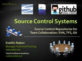
Automation Totalflow Measurement & Control Systems FCU Uncertainty Contributors and Microprocessor Based Enhancements. DOWNSTREAM SYSTEM(S). PRIMARY DEVICE. SECONDARY DEVICE(S). TERTIARY DEVICE. Fluid Properties. A to D CONV. SYSTEM SCHEMATIC. sources of uncertainty.

E N D
Automation Totalflow Measurement & Control Systems FCU Uncertainty Contributors and Microprocessor Based Enhancements
DOWNSTREAMSYSTEM(S) PRIMARY DEVICE SECONDARY DEVICE(S) TERTIARY DEVICE Fluid Properties A to D CONV SYSTEM SCHEMATIC sources of uncertainty Grav, CO2, N2, Density, Viscosity, etc. P R I M A R Y ALGORITHMS MATH COMPUTATIONS DATA Analyzer(s) M E T E R INSTRUMENT(s) POWER SUPPLIES Temper- ature TRANSDUCERs/TRANSMITTERs Static Pressure ANALOG SCALING HDWR DIGITAL “SMART” COMPENSATION ALGORITHMS Analog SECONDARY DEVICES (P,T) SIGNAL CONDITIONER Diff Pressure Analog Transducers/Transmitters SYSTEM CLOCK OR DIGITAL INTERFACE ANALOG SCALING HDWR SECONDARY DEVICES (P,T) A to D CONV Digital Transducers/Transmitters DIGITAL “SMART” COMPENSATION ALGORITHMS Digital Link (Serial or Parallel) Areas Affected by the API MPMS 21.1 EGM Standard LEGEND ZONE 1 ZONE 2 NOTE : Each component in the system is subject to its own independent uncertainties. Total system uncertainty is the sum total of all component uncertainties. Component can exist in ZONE 1 and/or ZONE 2 COMPONENT COMPONENT Optional Component or Zone
DOWNSTREAMSYSTEM(S) PRIMARY DEVICE SECONDARY DEVICE(S) TERTIARY DEVICE Fluid Properties A to D CONV SYSTEM SCHEMATIC sources of uncertainty Grav, CO2, N2, Density, Viscosity, etc. P R I M A R Y ALGORITHMS MATH COMPUTATIONS DATA Analyzer(s) M E T E R INSTRUMENT(s) POWER SUPPLIES Temper- ature TRANSDUCERs/TRANSMITTERs Static Pressure ANALOG SCALING HDWR DIGITAL “SMART” COMPENSATION ALGORITHMS Analog SECONDARY DEVICES (P,T) SIGNAL CONDITIONER Diff Pressure Analog Transducers/Transmitters SYSTEM CLOCK OR DIGITAL INTERFACE ANALOG SCALING HDWR SECONDARY DEVICES (P,T) A to D CONV Digital Transducers/Transmitters CONTAINED IN TOTALFLOW’s COMPENSATED AMU. DIGITAL “SMART” COMPENSATION ALGORITHMS Digital Link (Serial or Parallel) LEGEND ZONE 1 ZONE 2 NOTE : Each component in the system is subject to its own independent uncertainties. Total system uncertainty is the sum total of all component uncertainties. Component can exist in ZONE 1 and/or ZONE 2 COMPONENT COMPONENT Optional Component or Zone
DOWNSTREAMSYSTEM(S) PRIMARY DEVICE SECONDARY DEVICE(S) TERTIARY DEVICE Fluid Properties A to D CONV SYSTEM SCHEMATIC sources of uncertainty Grav, CO2, N2, Density, Viscosity, etc. P R I M A R Y ALGORITHMS, MATH COMPUTATIONS & DATA Analyzer(s) M E T E R INSTRUMENT(s) POWER SUPPLIES Temper- ature TRANSDUCERs/TRANSMITTERs Static Pressure ANALOG SCALING HDWR DIGITAL “SMART” COMPENSATION ALGORITHMS Analog SECONDARY DEVICES (P,T) SIGNAL CONDITIONER Diff Pressure Analog Transducers/Transmitters SYSTEM CLOCK OR DIGITAL INTERFACE ANALOG SCALING HDWR SECONDARY DEVICES (P,T) A to D CONV Digital Transducers/Transmitters DIGITAL “SMART” COMPENSATION ALGORITHMS Digital Link CONTAINED IN TOTALFLOW’s 6400 Digital Board (Serial or Parallel) LEGEND ZONE 1 ZONE 2 NOTE : Each component in the system is subject to its own independent uncertainties. Total system uncertainty is the sum total of all component uncertainties. Component can exist in ZONE 1 and/or ZONE 2 COMPONENT COMPONENT Optional Component or Zone
DOWNSTREAMSYSTEM(S) PRIMARY DEVICE SECONDARY DEVICE(S) TERTIARY DEVICE Fluid Properties A to D CONV SYSTEM SCHEMATIC sources of uncertainty Grav, CO2, N2, Density, Viscosity, etc. P R I M A R Y ALGORITHMS MATH COMPUTATIONS DATA Analyzer(s) M E T E R INSTRUMENT(s) POWER SUPPLIES Temper- ature TRANSDUCERs/TRANSMITTERs Static Pressure ANALOG SCALING HDWR DIGITAL “SMART” COMPENSATION ALGORITHMS Analog SECONDARY DEVICES (P,T) SIGNAL CONDITIONER Diff Pressure Analog Transducers/Transmitters SYSTEM CLOCK OR DIGITAL INTERFACE ANALOG SCALING HDWR SECONDARY DEVICES (P,T) A to D CONV Digital Transducers/Transmitters DIGITAL “SMART” COMPENSATION ALGORITHMS Digital Link Subject To Flowrate Equation Uncertaintiy Analysis (Serial or Parallel) LEGEND ZONE 1 ZONE 2 NOTE : Each component in the system is subject to its own independent uncertainties. Total system uncertainty is the sum total of all component uncertainties. Component can exist in ZONE 1 and/or ZONE 2 COMPONENT COMPONENT Optional Component or Zone
Analog Measurement Unit (AMU)Foundation for Accuracy • “Smart” Static and Differential Pressure Transducers • Transducers and Analog Electronics Characterized • Factory Calibrated • 0.2% Lin,Hyst,Repeat(0.05% available) • 0.25% Total Temp Effect OverRange (-29 to 60 C / -20 to 140 F) • 18 Bit A/D Conversion(0.0004 % Resolution) • EMI/RFI Shielded • 26 - 1000 MHz @ 30 v/m • Digital link to main board
Software Correction ofTransducer Errors • With a microprocessor some of the transducer errors can be greatly reduced. • Totalflow flow computer software enhances transducer performace by correcting for • Temperature effects • Non-linearity • Static Pressure affect on Differential Pressure
Software Corrections - Linearity • The closeness to which a transducer output follows a straight line from zero to full scale. • Can be reduced by a factor of four when the linearity curve is a parabola by using a 3 point calibration (2 line approximation) • Can be further reduced by increasing number of calibration points (straight line approximations).
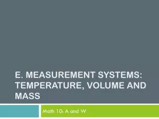
Software Corrections - Temperature Effect • The output of a transducer varies with temperature. • Typical temperature effect error =+ or - 1.0% per 100 degrees F • Can be corrected by characterization • 40 to 60 hour temperature step test performed • pressures also stepped during temperature steps • compared to known source (usually NIST, etc.) • errors are mathematically reduced through curve fit algorithms (matrix)
Software Corrections -Temperature Effect Example: Errors caused by temperature alone are 3% before compensationover temperature band of -20 to +140 deg. F 0.0 -0.5 -1.0 Percent Error -1.5 -2.0 -2.5 -3.0
Software Corrections - Temperature Effect Example: Errors are reduced to below 0.015% after compensation, over temperature band of -20 to +140 deg. F
Software Corrections - Static Pressure Effect • Differential pressure transducer output changes when subjected to static pressure different than the pressure existing at time of calibration. • 100 “ calibration pressure has placed 3.6 PSI on one side of the transducer’s housing (27.7 “H2O = 1 PSI) • When higher pressure is applied mechanical variations inside the transducer shift the differential pressure transducer’s output • The same phenomena exists, even if transducer is “zeroed” under pressure. A shift in static pressure away from the zero point will still induce a change in the differential pressure transducer output.
Software Corrections - Static Pressure Effect + Static Pressures DP Shift - Totalflow’s Correction cheme
Other Key Tertiary Device Elements • Volume Algorithms/Equations • Equations are explicit implementations, not table driven approximations • Participated in API round robin for AGA-3-92 • API sought +/- 50 ppm deviation tolerance • 10,080 calculation sets were tested • Totalflow’s deviations were within +/- 5 ppm • Along with whole flow computer, algorithms subjected to flow laboratory testing • Stable timebase (over temperature) to assure accurate integration • +/- 2 minutes per month (+/- 0.00046% of reading)