Download
1 / 106
1.15k likes | 1.47k Views
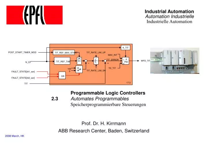
Industrial Automation Automation Industrielle Industrielle Automation. K_TIT. POST_START_TIMER_MOD. TIT_RATE_LIM_UP. TIT_REF_MAX_START. MAX_INT. lim. P. TIT_ERROR. I. WFD_TIT. TIT_REF_TAB. PID. N_GT. D. TD_TIT. 100. TIT_RATE_LIM_DN. 0. FAULT_STATE[tit1_oor]. OR.

E N D
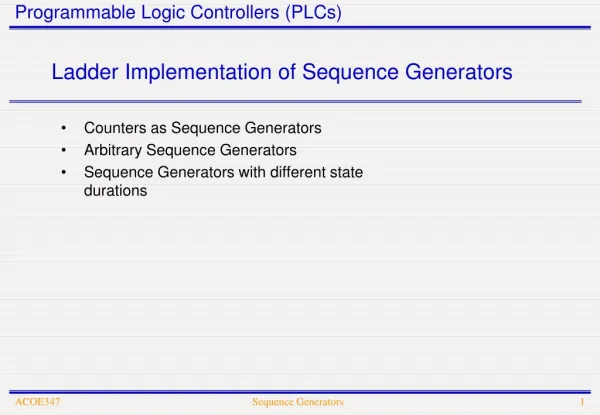
Industrial AutomationAutomation IndustrielleIndustrielle Automation K_TIT POST_START_TIMER_MOD TIT_RATE_LIM_UP TIT_REF_MAX_START MAX_INT lim P TIT_ERROR I WFD_TIT TIT_REF_TAB PID N_GT D TD_TIT 100 TIT_RATE_LIM_DN 0 FAULT_STATE[tit1_oor] OR FAULT_STATE[tit2_oor] 17.3 TIT Programmable Logic Controllers 2.3 Automates Programmables Speicherprogrammierbare Steuerungen Prof. Dr. H. Kirrmann ABB Research Center, Baden, Switzerland 2008 March, HK
2.3.1 PLCs: Definition and Market • 2.1 Instrumentation • 2.2 Control • 2.3 Programmable Logic Controllers • 2.3.1 PLCs: Definition and Market • 2.3.2 PLCs: Kinds • 2.3.3 PLCs: Functions and construction • 2.3.4 Continuous and Discrete Control • 2.3.5 PLC Programming Languages • 2.3.5.1 IEC 61131 Languages • 2.3.5.2 Function blocks • 2.3.5.3 Program Execution2.3.5.4 Input / Output • 2.3.5.5 Structured Text • 2.3.5.6 Sequential Function Charts2.3.5.7 Ladder Logic • 2.3.5.8 Instruction Lists • 2.3.5.9 Programming environment
PLC = Programmable Logic Controller: Definition AP = Automates Programmables industriels SPS = Speicherprogrammierbare Steuerungen Definition: “small computers, dedicated to automation tasks in an industrial environment" Formerly: cabled relay control (hence 'logic'), analog (pneumatic, hydraulic) governors Today: real-time (embedded) computer with extensive input/output Function: Measure, Control, Protect Distinguish Instrumentation flow meter, temperature, position,…. but also actors (pump, …) Control programmable logic controllers with digital peripherals & field bus Visualization HMI* in PLCs (when it exists) is limited to control of operator displays *Human Machine Interface
PLC is a cabinet CPU1 CPU2 serial connections redundant field bus connection inputs/outputs
PLC: functions (Messen, Schützen, Regeln = MSR) PLC = PMC: Protection, Measurement and Control • Measure • Control (Command and Regulation) • Protection • Event Logging • Communication • Human interface
PLC: Characteristics • large number of peripherals: 20..100 I/O per CPU, high density of wiring, easy assembly. • binary and analog Input/Output with standard levels • located near the plant (field level), require robust construction, protection against dirt, water and mechanical threats, electro-magnetic noise, vibration, extreme temperature range (-30C..85C) • programming: either very primitive with hand-help terminals on the target machine itself, or with a lap-top able to down-load programs. • network connection is becoming common, allowing programming on workstations. • field bus connection for remote I/Os • primitive Man-Machine interface, either through LCD-display or connection of a laptopover serial lines (RS232). • economical - €1000.- .. €15'000.- for a full crate. • the value is in the application software (licenses €20'000 ..€50'000)
PLC: Location in the control architecture Enterprise Network Engineer station Operator station Supervisor Station gateway Control Bus (e.g. Ethernet) PLC large PLCs Control Station PLC COM1 COM 2 CPU COM1 COM1 with Field Bus COM 2 gateway I/O CPU CPU I/O I/O I/O I/O I/O I/O I/O I/O I/O direct I/O Field Bus Field Bus directly connected I/O COM COM COM I/O I/O I/O I/O I/O I/O I/O COM CPU CPU CPU COM Field Stations FB Field Devices gateway small PLC very simple PLCs Sensor Bus (e.g. ASI)
PLC: manufacturers Switzerland SAIA, Weidmüller Europe: Siemens (60% market share) [Simatic], ABB (includes Hartmann&Braun, Elsag-Bailey, SattControl,…) [IndustrialIT], Groupe Schneider [Télémécanique], WAGO, Phoenix Contact ... World Market: GE-Fanuc, Honeywell, Invensys (Foxboro) Rockwell, (Allen-Bradley,…) Emerson (Fisher Control, Rosemount, Westinghouse) Hitachi, Toshiba, Fujitsu, Yokogawa … large number of bidders, fusions and acquisitions in the last years. Distinguish PLCs for the open market (OEM) and proprietary PLCs
2.3.3 PLCs: Kinds • 2.1 Instrumentation • 2.2 Control • 2.3 Programmable Logic Controllers • 2.3.1 PLCs: Definition and Market • 2.3.2 PLCs: Kinds • 2.3.3 PLCs: Functions and construction • 2.3.4 Continuous and Discrete Control • 2.3.5 PLC Programming Languages • 2.3.5.1 IEC 61131 Languages • 2.3.5.2 Function blocks • 2.3.5.3 Program Execution2.3.5.4 Input / Output • 2.3.5.5 Structured Text • 2.3.5.6 Sequential Function Charts2.3.5.7 Ladder Logic • 2.3.5.8 Instruction Lists • 2.3.5.9 Programming environment
Kinds of PLC (1) Compact Monolithic construction Monoprocessor Fieldbus connection Fixed casing Fixed number of I/O (most of them binary) No process computer capabilities (no MMC) Typical product: Mitsubishi MELSEC F, ABB AC31, SIMATIC S7 (2) Modular PLC Modular construction (backplane) One- or multiprocessor system Fieldbus and LAN connection 3U or 6U rack, sometimes DIN-rail Large variety of input/output boards Connection to serial bus Small MMC function possible Typical products: SIMATIC S5-115, Hitachi H-Serie, ABB AC110 (3) Soft-PLC Windows NT or CE-based automation products Direct use of CPU or co-processors
Modular PLC • tailored to the needs of an application development environment RS232 • housed in a 19" (42 cm) rack (height 6U ( = 233 mm) or 3U (=100mm) • high processing power (several CPU) LAN • large choice of I/O boards backplane parallel bus • concentration of a large number of I/O courtesy ABB • interface boards to field busses fieldbus • requires marshalling of signals Power Supply • primitive or no HMI CPU CPU Analog I/O Binary I/O • cost effective if the rack can be filled fieldbus • supply 115-230V~ , 24V= or 48V= (redundant) • cost ~ €10’000 for a filled crate
Small modular PLC courtesy ABB courtesy Backmann mounted on DIN-rail, 24V supply cheaper (€5000) not water-proof, no ventilator extensible by a parallel bus (flat cable or rail)
Specific controller (railways) data bus three PLCs networked by a data bus. special construction: no fans, large temperature range, vibrations
Compact or modular ? field bus extension € compact PLC (fixed number of I/Os) modular PLC (variable number of I/Os Limit of local I/O # I/O modules
Industry- PC courtesy INOVA courtesy MPI Wintel architecture (but also: Motorola, PowerPC), MMI offered (LCD..) Limited modularity through mezzanine boards (PC104, PC-Cards, IndustryPack) Backplane-mounted versions with PCI or Compact-PCI Competes with modular PLC no local I/O, fieldbus connection instead, costs: € 2000.-
12 23 2 2 4 3 3 Soft-PLC (PC as PLC) • PC as engineering workstation • PC as human interface (Visual Basic, Intellution, Wonderware) • PC as real-time processor (Soft-PLC) • PC assisted by a Co-Processor (ISA- or PC104 board) • PC as field bus gateway to a distributed I/O system I/O modules
Compact PLC courtesy ABB courtesy ABB courtesy ABB Monolithic (one-piece) construction Fixed casing Fixed number of I/O (most of them binary) No process computer capabilities (no MMC) Can be extended and networked by an extension (field) bus Sometimes LAN connection (Ethernet, Arcnet) Monoprocessor Typical product: Mitsubishi MELSEC F, ABB AC31, SIMATIC S7 costs: € 2000
Specific Controller (example: Turbine) tailored for a specific application, produced in large series Programming port Relays and fuses Thermocouple inputs binary I/Os, CAN field bus RS232 to HMI courtesy Turbec cost: € 1000.-
Protection devices measurement transformers communication to operator substation Human interface for status and settings Ir Is It Ur Programming interface Us UT trip relay Protection devices are highly specialized PLCs that measure the current and voltages in an electrical substation, along with other statuses (position of the switches,…) to detect situations that could endanger the equipment (over-current, short circuit, overheat) and triggers the circuit breaker (“trip”) to protect the substation. In addition, it records disturbances and sends the reports to the substation’s SCADA. Sampling: 4.8 kHz, reaction time: < 5 ms. costs: € 5000
Market share % installed PLCs Micro: 15 to 128 I/O points Medium: 128 - 512 I/O points Large: > 512 I/O points Nano: < 15 I/O points PC-based Software PLC Embedded control 32% 29% 20% 7% 6% 4% 2% Source: Control Engineering, Reed Research, 2002-09
Global players Total sales in 2004: 7’000 Mio € Source: ARC Research, 2005-10
Comparison Criteria – Example Siemens Hitachi Brand Number of Points 1024 640 16 KB Memory 10 KB • Ladder Logic Programming Language • Ladder logic • Instructions • Instructions • Logic symbols • Logic symbols • Basic • Hand-terminal • Hand-terminal Programming Tools • Graphic on PC • Graphic on PC Download no yes Real estate per 250 I/O 2678 cm2 1000 cm2 Label surface 5.3 mm2 6 mm2 per line/point 7 characters 6 characters Network 10 Mbit/s 19.2 kbit/s Mounting DIN rail cabinet
2.3.3 PLCs: Function and construction • 2.1 Instrumentation • 2.2 Control • 2.3 Programmable Logic Controllers • 2.3.1 PLCs: Definition and Market • 2.3.2 PLCs: Kinds • 2.3.3 PLCs: Functions and construction • 2.3.4 Continuous and Discrete Control • 2.3.5 PLC Programming Languages • 2.3.5.1 IEC 61131 Languages • 2.3.5.2 Function blocks • 2.3.5.3 Program Execution2.3.5.4 Input / Output • 2.3.5.5 Structured Text • 2.3.5.6 Sequential Function Charts2.3.5.7 Ladder Logic • 2.3.5.8 Instruction Lists • 2.3.5.9 Programming environment
General PLC architecture RS 232 Ethernet CPU Real-TimeClock ROM flash EPROM serial port controller ethernet controller extension bus buffers parallel bus fieldbus controller analog- digital converters digital- analog converters Digital Output Digital Input external I/Os signal conditioning power amplifiers signalconditioning relays direct Inputs and Outputs field bus
y time The signal chain within a PLC y(i) y(i) y time time time analogvariable (e.g. 4..20mA) filtering & scaling sampling analog-digital converter digital-analogconverter amplifier analogvariable e.g. -10V..10V 011011001111 processing 1 binaryvariable (e.g. 0..24V) filtering sampling transistororrelay binaryvariable 0001111 non-volatile memory counter
Signal chain in a protection device Inputtransformer Anti aliasing filter Sample and holdA/D conversion Digital filter Protectionalgorithm Outputdriver U/I Trip CPU A/D reaction < 10 ms f = 300 -1200 Hz f = 200 kHz f = 100 kHz f = 1 MHz
2.3.4 Continuous and discrete control • 2.1 Instrumentation • 2.2 Control • 2.3 Programmable Logic Controllers • 2.3.1 PLCs: Definition and Market • 2.3.2 PLCs: Kinds • 2.3.3 PLCs: Functions and construction • 2.3.4 Continuous and Discrete Control • 2.3.5 PLC Programming Languages • 2.3.5.1 IEC 61131 Languages • 2.3.5.2 Function blocks • 2.3.5.3 Program Execution2.3.5.4 Input / Output • 2.3.5.5 Structured Text • 2.3.5.6 Sequential Function Charts2.3.5.7 Ladder Logic • 2.3.5.8 Instruction Lists • 2.3.5.9 Programming environment
Matching the analog and binary world discrete control analog regulation
PLC evolution Binary World Analog World relay controls, Pneumatic and electromechanical Relay control pneumatic sequencer controllers I1 A B C P1 P2 Regulation, controllers combinatorial sequential discrete processes continuous processes Programmable Logic Controllers (Speicherprogrammierbare Steuerungen, Automates Programmables)
Continuous Plant (reminder) Example: traction motors, ovens, pressure vessel,... The state of continuous plants is described by continuous (analog) state variables like temperature, voltage, speed, etc. There exist a fixed relationship between input and output,described by a continuous model in form of a transfer function F. This transfer function can be expressed by a set of differential equations. If equations are linear, the transfer function may expressed as Laplace or Z-transform. y (1+Ts) F(s) = x y time (1+T1s + T2s2) Continuous plants are normally reversible and monotone. This is the condition to allow their regulation. The time constant of the control system must be at least one order of magnitude smaller than the smallest time constant of the plant. the principal task of the control system for a continuous plant is its regulation.
Discrete Plant (reminder) Examples: Elevators, traffic signaling, warehouses, etc. The plant is described by variables which take well-defined, non-overlapping values.The transition from one state to another is abrupt, it is caused by an external event. Discrete plants are normally reversible, but not monotone, i.e. negating the event which caused a transition will not revert the plant to the previous state. Example: an elevator doesn't return to the previous floor when the button is released. Discrete plants are described e.g. by finite state machines or Petri nets. the main task of a control system with discrete plants is its sequential control.
Continuous and Discrete Control (comparison) "sequential" "combinatorial"1) e.g. ladder logic, CMOS logic e.g. GRAFCET, Petri Nets A B Out = A · B ladder NOT C A logic B Out = (A + B) · C I1 analog building blocs P1 P2 1) not really combinatorial: blocs may have memory
2.3.5 Programming languages • 2.1 Instrumentation • 2.2 Control • 2.3 Programmable Logic Controllers • 2.3.1 PLCs: Definition and Market • 2.3.2 PLCs: Kinds • 2.3.3 PLCs: Functions and construction • 2.3.4 Continuous and Discrete Control • 2.3.5 Programming languages • 2.3.5.1 IEC 61131 Languages • 2.3.5.2 Function blocks • 2.3.5.3 Program Execution2.3.5.4 Input / Output • 2.3.5.5 Structured Text • 2.3.5.6 Sequential Function Charts2.3.5.7 Ladder Logic • 2.3.5.8 Instruction Lists • 2.3.5.9 Programming environment
"Real-Time" languages Extend procedural languages to express time languages developed for cyclic execution and real-time (“introduce programming constructs to ("application-oriented languages") influence scheduling and control flow”) • ADA • ladder logic • Real-Time Java • function block language MARS (TU Wien) • • instruction lists • Forth • GRAFCET • “C” with real-time features • SDL • etc… etc... could not impose themselves wide-spread in the control industry. Now standardized as IEC 61131
The long march to IEC 61131 NEMA Programmable Controllers Committee formed (USA) GRAFCET (France) DIN 40719, Function Charts (Germany) NEMA ICS-3-304, Programmable Controllers (USA) IEC SC65A/WG6 formed DIN 19 239, Programmable Controller (Germany) IEC 65A(Sec)38, Programmable Controllers MIL-STD-1815 Ada (USA) IEC SC65A(Sec)49, PC Languages IEC SC65A(Sec)67 IEC 848, Function Charts IEC 64A(Sec)90 IEC 1131-3 Type 3 report recommendation IEC 61131-3 name change 70 77 78 79 80 81 82 83 84 85 86 87 88 89 90 91 92 93 94 95 96 Source: Dr. J. Christensen it took 20 years to make that standard…
START STEP T1 N D1_READY ACTION D1 STEP A ACTION D2 D D2_READY T2 N D3_READY ACTION D3 STEP B ACTION D4 D D4_READY T3 VAR CONSTANT X : REAL := 53.8 ; Z : REAL; END_VAR VAR aFB, bFB : FB_type; END_VAR bFB(A:=1, B:=‘OK’); Z := X - INT_TO_REAL (bFB.OUT1); IF Z>57.0 THEN aFB(A:=0, B:=“ERR”); ELSE aFB(A:=1, B:=“Z is OK”); END_IF The five IEC 61131-3 Programming languages http://www.isagraf.com graphical languages Function Block Diagram (FBD) Sequential Flow Chart (SFC) AUTO CALC1 PUMP DI CALC DO >=1 IN1 V OUT V MAN_ON IN2 ACT Ladder Diagram (LD) CALC1 CALC PUMP AUTO IN1 OUT textual languages Structured Text (ST) ACT IN2 MAN_ON Instruction List (IL) A: LD %IX1 (* PUSH BUTTON *) ANDN %MX5 (* NOT INHIBITED *) ST %QX2 (* FAN ON *)
Importance of IEC 61131 IEC 61131-3 is the most important automation language in industry. 80% of all PLCs support it, all new developments base on it. Depending on the country, some languages are more popular.
2.4.2.1 Function Blocks Language • 2.1 Instrumentation • 2.2 Control • 2.3 Programmable Logic Controllers • 2.3.1 PLCs: Definition and Market • 2.3.2 PLCs: Kinds • 2.3.3 PLCs: Functions and construction • 2.3.4 Continuous and Discrete Control • 2.3.5 PLC Programming Languages • 2.3.5.1 IEC 61131 Languages • 2.3.5.2 Function blocks language • 2.3.5.3 Program Execution2.3.5.4 Input / Output • 2.3.5.5 Structured Text • 2.3.5.6 Sequential Function Charts2.3.5.7 Ladder Logic • 2.3.5.8 Instruction Lists • 2.3.5.9 Programming environment
Function Block Languages (Funktionsblocksprache, langage de blocs de fonctions)(Also called "Function Chart" or "Function Plan" - FuPla) The function block languages express "combinatorial" programs in a way similar to electronic circuits. They draw on a large variety of predefined and custom functions This language is similar to the Matlab / Simulink language used in simulations
Function Block Examples Example 1: A & C B Example 2: external outputs external inputs T Trigger & S Spin Running R Reset Function blocks is a graphical programming language, which is akin to theelectrical and block diagrams of the analog and digital technique. It mostly expresses combinatorial logic, but its blocks may have a memory (e.g. flip-flops).
Function Block Elements parameters Function block "continuously" Example PID set point executing block, independent, measurement motor no side effects The block is defined by its: • Data flow interface (number and type of input/output signals) • Black-Box-Behavior (functional semantic, e.g. in textual form). Signals Connections that carry a pseudo-continuous data flow. Connects the function blocks. set point (set point) Example (set point)
Function Block Rules There exist exactly two rules for connecting function blocks by signals (this is the actual programming): • Each signal is connected to exactly one source. This source can be the output of a function block or a plant signal. • The type of the output pin, the type of the input pin and the signal type must be identical. For convenience, the function plan should be drawn so the signals flow from left to right and from top to bottom. Some editors impose additional rules. Retroactions are exception to this rule. In this case, the signal direction is identified by an arrow. (Some editors forbid retroactions - use duplicates instead). a b x z c y
Types of Programming Organisation Units (POUs) 1) “Functions” - are part of the base library. - have no memory. Example are: adder, multiplier, selector,.... 2) “Elementary Function Blocks” (EFB) - are part of the base library - have a memory ("static" data). - may access global variables (side-effects !) Examples: counter, filter, integrator,..... 3) “Programs” (Compound blocks) - user-defined or application-specific blocks - may have a memory - may be configurable (control flow not visible in the FBD Examples: PID controller, Overcurrent protection, Motor sequence (a library of compound blocks may be found in IEC 61804-1)
Function Block library The programmer chooses the blocks in a block library, similarly to the hardware engineer who chooses integrated circuits out of the catalogue. This library indicates the pinning of each block, its semantics and the execution time. The programmer may extend the library by defining function block macros out of library elements. If some blocks are often used, they will be programmed in an external language (e.g. “C”, micro-code) following strict rules.
IEC 61131-3 library (extract) binary elements analog elements greater equal GE greater than GT adder AND GT ADD and less than LT less equal LE OR subtractor SUB or TON timer on IN Q delay PT ET XOR exclusive-or MUL multiplier CTU SR CU up counter divider DIV S1 Q flip-flop RESET (CTD counter down) R Q0 ET PV INT R_TRIG bool positive SEL integrator selector (1:2) Reset S1 Q0 edge PresetVal In int (if reset) {out = PresetVal;} MUX multiplexer(1:N) The number of inputs or outputs and their type is restricted. The execution time of each block depends on the block type, the number of inputs and on the processor.
Exercise: Tooth saw generator exercise: build a tooth-saw (asymmetric) generator with the IEC 61131 elements of the preceding page 5s 12s 75% 0% -25%
Library functions for discrete plants Basic blocks logical combinations (AND, OR, NOT, EXOR)Flip-flopSelector m-out-of-n Multiplexer m-to-nTimerCounterMemorySequencing Compound blocks Display Manual input, touch-screen Safety blocks (interlocking) Alarm signaling Logging
Analog function blocks for continuous control Basic blocks Summator / SubtractorMultiplier / DividerIntegrator / DifferentiatorFilter Minimal value, Maximum valueRadixFunction generator Regulation Functions P, PI, PID, PDT2 controllerFixed set-pointRatio and multi-component regulationParameter variation / setting2-point regulation3-point regulationOutput value limitationRamp generatorAdaptive regulationDrive Control