Download
1 / 27
270 likes | 443 Views
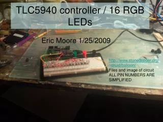
TLC5940 controller / 16 RGB LEDs. http://www.stonedcoder.org/~druid/balloon/ Files and image of circuit ALL PIN NUMBERS ARE SIMPLIFIED. Eric Moore 1/25/2009. Materials. 1 Breadboard Jumper cables – either bought or made 1 Arduino 16 RGB LEDs 3 resistors – anything with a k that works

E N D
TLC5940 controller / 16 RGB LEDs http://www.stonedcoder.org/~druid/balloon/ Files and image of circuit ALL PIN NUMBERS ARE SIMPLIFIED Eric Moore 1/25/2009
Materials • 1 Breadboard • Jumper cables – either bought or made • 1 Arduino • 16 RGB LEDs • 3 resistors – anything with a k that works You need a laptop and cable to load the code in to the arduino. If you haven’t done that before, stop and follow the tutorials at arduino.cc
Insert chip on board, leave 1 pin open on the left, and 2 open between chips – use ruler / straightedge to bend pins if needed
Note the 2 spaces between chips, now tie pins 1 and 14 on each chip to pins 1 and 16 on the opposite side of the breadboard
Note the yellow lines, now we will add our power lines to the chip
Now pins 1, 2, 3, 4, 5, 6, 7, 8, 10, and 11 should be connected on the third chip
When you are done, your board should look like this, hopefully cleaner
Pins 9 and 10 on the ‘duino go to pins 5 and 6 on the first chip
Connect red to anode AKA high (+5 or +3.3)Connect blue to black cathode AKA low or ground
Now for the LEDs!The long leg is the anode, and run to high.
Bend the anode (long leg) away from the other legs, making sure that the pin that is alone on one side is to your left, and you bend toward you. This ensures all the LEDs are in the same order.
Insert the LED into breadboard pins 1-2-3 with anode in the RED bus
Connect the RED bus on one side of the board with the RED bus you just inserted all the anodes in to.