Download
1 / 116
1.16k likes | 1.34k Views
Chapter 13 Controller Area Network. History of CAN (Controller Area Network). It was created in mid-1980s for automotive applications by Robert Bosch. Design goal was to make automobiles more reliable, safer, and more fuel efficient.

E N D
History of CAN (Controller Area Network) • It was created in mid-1980s for automotive applications by Robert Bosch. • Design goal was to make automobiles more reliable, safer, and more fuel efficient. • The latest CAN specification is the version 2.0 made in 1991.
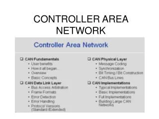
Layered Approach in CAN (1 of 3) • Only the logical link and physical layers are described. • Data link layer is divided into two sublayers: logical link control (LLC) and medium access control (MAC). • LLC sublayer deals with message acceptance filtering, overload notification, and error recovery management. • MAC sublayer presents incoming messages to the LLC sublayer and accepts messages to be transmitted forward by the LLC sublayer. • MAC sublayer is responsible for message framing, arbitration, acknowledgement, error detection, and signaling. • MAC sublayer is supervised by the fault confinement mechanism.
Layered Approach in CAN (2 of 3) • The physical layer defines how signals are actually transmitted, dealing with the description of bit timing, bit encoding, and synchronization. • CAN bus driver/receiver characteristics and the wiring and connectors are not specified in the CAN protocol. • System designer can choose from several different media to transmit the CAN signals.
General Characteristics of CAN (1 of 3) • Carrier Sense Multiple Access with Collision Detection (CSMA/CD) • Every node on the network must monitor the bus (carrier sense) for a period of no activity before trying to send a message on the bus. • Once the bus is idle, every node has equal opportunity to transmit a message. • If two nodes happen to transmit simultaneously, a nondestructive arbitration method is used to decide which node wins.
General Characteristics of CAN (2 of 3) • Message-Based Communication • Each message contains an identifier. • Identifiers allow messages to arbitrate and also allow each node to decide whether to work on the incoming message. • The lower the value of the identifier, the higher the priority of the identifier. • Each node uses one or more filters to compare the incoming messages to decide whether to take actions on the message. • CAN protocol allows a node to request data transmission from other nodes. • There is no need to reconfigure the system when a new node joins the system.
General Characteristics of CAN (3 of 3) • Error Detection and Fault Confinement • The CAN protocol requires each node to monitor the CAN bus to find out if the bus value and the transmitted bit value are identical. • The CRC checksum is used to perform error checking for each message. • The CAN protocol requires the physical layer to use bit stuffing to avoid long sequence of identical bit value. • Defective nodes are switched off from the CAN bus.
Types of CAN Messages (1 of 2) • Data frame • Remote frame • Error frame • Overload frame
Types of CAN Messages (2 of 2) • Two states of CAN bus • Recessive: high or logic 1 • Dominant: low or logic 0
Data Frame • A data frame consists of seven fields: start-of-frame, arbitration, control, data, CRC, ACK, and end-of-frame.
Start of Frame • A single dominant bit to mark the beginning of a data frame. • All nodes have to synchronize to the leading edge caused by this field.
Arbitration Field • There are two formats for this field: standard format and extended format. • The identifier of the standard format corresponds to the base ID in the extended format. • The RTR bit is the remote transmission request and must be 0 in a data frame. • The SRR bit is the substitute remote request and is recessive. • The IDE field indicates whether the identifier is extended and should be recessive in the extended format. • The extended format also contains the 18-bit extended identifier.
Control Field • Contents are shown in figure 13.4. • The first bit is IDE bit for the standard format but is used as reserved bit r1 in extended format. • r0 is reserved bit. • DLC3…DLC0 stands for data length and can be from 0000 (0) to 1000 (8).
Data Field • May contain 0 to 8 bytes of data
CRC Field • It contains the 16-bit CRC sequence and a CRC delimiter. • The CRC delimiter is a single recessive bit.
ACK Field • Consists of two bits • The first bit is the acknowledgement bit. • This bit is set to recessive by the transmitter, but will be reset to dominant if a receiver acknowledges the data frame. • The second bit is the ACK delimiter and is recessive.
Remote Frame • Used by a node to request other nodes to send certain type of messages • Has six fields as shown in Figure 13.7 • These fields are identical to those of a data frame with the exception that the RTR bit in the arbitration field is recessive in the remote frame.
Error Frame • This frame consists of two fields. • The first field is given by the superposition of error flags contributed from different nodes. • The second field is the error delimiter. • Error flag can be either active-error flag or passive-error flag. • Active error flag consists of six consecutive dominant bits. • Passive error flag consists of six consecutive recessive bits. • The error delimiter consists of eight recessive bits.
Overload Frame • Consists of two bit fields: overload flag and overload delimiter • Three different overload conditions lead to the transmission of the overload frame: • Internal conditions of a receiver require a delay of the next data frame or remote frame. • At least one node detects a dominant bit during intermission. • A CAN node samples a dominant bit at the eighth bit (i.e., the last bit) of an error delimiter or overload delimiter. • Format of the overload frame is shown in Figure 13.9. • The overload flag consists of six dominant bits. • The overload delimiter consists of eight recessive bits.
Interframe Space (1 of 2) • Data frames and remote frames are separated from preceding frames by the interframe space. • Overload frames and error frames are not preceded by an interframe space. • The formats for interframe space is shown in Figure 13.10 and 13.11.
Interframe Space (2 of 2) • The intermission subfield consists of three recessive bits. • During intermission no node is allowed to start transmission of the data frame or remote frame. • The period of bus idle may be of arbitrary length. • After an error-passive node has transmitted a frame, it sends eight recessive bits following intermission, before starting to transmit a new message or recognizing the bus as idle.
Message Filtering • A node uses filter (s) to decide whether to work on a specific message. • Message filtering is applied to the whole identifier. • A node can optionally implement mask registers that specify which bits in the identifier are examined with the filter. • If mask registers are implemented, every bit of the mask registers must be programmable.
Bit Stream Encoding • The frame segments including start-of-frame, arbitration field, control field, data field, and CRC sequence are encoded by bit stuffing. • Whenever a transmitter detects five consecutive bits of identical value in the bit stream to be transmitted, it inserts a complementary bit in the actual transmitted bit stream. • The remaining bit fields of the data frame or remote frame (CRC delimiter, ACK field and end of frame) are of fixed form and not stuffed. • The error frame and overload frame are also of fixed form and are not encoded by the method of bit stuffing. • The bit stream in a message is encoded using the non-return-to-zero (NRZ) method. • In the non-return-to-zero encoding method, a bit is either recessive or dominant.
Errors (1 of 3) • Error handling • CAN recognizes five types of errors. • Bit error • A node that is sending a bit on the bus also monitors the bus. • When the bit value monitored is different from the bit value being sent, the node interprets the situation as an error. • There are two exceptions to this rule: • A node that sends a recessive bit during the stuffed bit-stream of the arbitration field or during the ACK slot detects a dominant bit. • A transmitter that sends a passive-error flag detects a dominant bit.
Errors (2 of 3) • Stuff error • Six consecutive dominant or six consecutive recessive levels occurs in a message field. • CRC error • CRC sequence in the transmitted message consists of the result of the CRC calculation by the transmitter. • The receiver recalculates the CRC sequence using the same method but resulted in a different value. This is detected as a CRC error.
Errors (3 of 3) • Form error • Detected when a fixed-form bit field contains one or more illegal bits • Acknowledgement error • Detected whenever the transmitter does not monitor a dominant bit in the ACK slot • Error Signaling • A node that detects an error condition and signals the error by transmitting an error flag • An error-active node will transmit an active-error flag. • An error-passive node will transmit a passive-error flag.
Fault Confinement • A node may be in one of the three states: error-active, error-passive, and bus-off. • A CAN node uses an error counter to control the transition among these three states. • CAN protocol uses 12 rules to control the increment and decrement of the error counter. • When the error count is less than 128, a node is in error-active state. • When the error count equals or exceeds 128 but not higher 255, the node is in error-passive state. • When the error count equals or exceeds 256, the node is in bus off state. • An error-active node will transmit an active-error frame when detecting an error. • An error-passive node will transmit a passive-error frame when detecting an error. • A bus-off node is not allowed to take part in bus communication.
CAN Message Bit Timing • The setting of a bit time in a CAN system must allow a bit sent out by the transmitter to reach the far end of the CAN bus and allow the receiver to send back acknowledgement and reach the transmitter. • The number of bits transmitted per second is defined as the nominal bit rate.
Nominal Bit Time • The inverse of the nominal bit rate is the nominal bit time. • A nominal bit time is divided into four segments as shown in Figure 13.12.
Sync seg Segment • It is used to synchronize the various nodes on the bus. • An edge is expected to lie in this segment.
Prop-seg Segment • Used to compensate for the physical delay times within the network • Equals twice the sum of the signal’s propagation time on the CAN bus line, the comparator delay, and the output driver delay
Phase_seg1 and phase_seg2 • Used to compensate for edge phase errors • Both can be lengthened or shortened by synchronization
Sample Point • At the end of phase_seg1 segment. • Users can choose to take three samples instead of one. • A majority function determines the bit value when three samples are taken. • Each sample is separated by half time quantum from the next sample. • The time spent on determining the bit value is the information processing time.
Time Quantum • A fixed unit of time derived by dividing the oscillator period by a prescaler • Length of time segments • sync_seg is 1 time quantum long • prop_seg is programmable to be 1,2,…,8 time quanta long • phase_seg1 is programmable to be 1,2,…,8 time quanta long • phase_seg2 is programmable to be 2,3,…,8 time quanta long • Information processing time is fixed at 2 time quanta for the HCS12. • The total number of time quanta in a bit time must be programmable between 8 and 25.
Synchronization Issue • All CAN nodes must be synchronized while receiving a transmission. • The beginning of each received bit must occur during each node’s sync_seg segment. • Synchronization is needed to compensate for the difference in oscillator frequencies of each node, the change in propagation delay and other factors. • Two types of synchronizations are defined: hard synchronization and resynchronization. • Hard synchronization is performed at the beginning of a message frame, when each CAN node aligns the sync_seg of its current bit time to the recessive-to-dominant transition. • Resynchronization is performed during the remainder of the message frame whenever a change of bit value from recessive to dominant occurs outside the expected sync_seg segment.
Overview of the HCS12 CAN Module (1 of 2) • An HCS12 device may have from one to five on-chip CAN modules. • Each CAN module has five receive buffers with FIFO storage scheme and three transmit buffers. • Each of the three transmit buffers may be assigned with a local priority. • Maskable identifier filter supports two full size extended identifier filters (32-bit), four 16-bit filters, or eight 8-bit filters. • The CAN module has a programmable loopback mode that supports self-test operation. • The CAN module has a listen-only mode for monitoring of the CAN bus.
Overview of the HCS12 CAN Module (2 of 2) • The CAN module has separate signaling and interrupts for all CAN receiver and transmitter error states (warning, error passive, and bus off). • Clock signal for CAN bus can come from either the bus clock or oscillator clock. • The CAN module supports time-stamping for received and transmitted messages • The block diagram of a CAN module is shown in Figure 13.13. • The CAN module requires a transceiver (e.g., MCP2551, PCA82C250) to interface with the CAN bus. • A typical CAN bus system is shown in Figure 13.14. • The CAN module has a 16-bit free-running timer.
MSCAN Module Memory Map • Each CAN module occupies 64 bytes of memory space. • The MSCAN register organization is shown in Figure 13.15. • Each receive buffer and each transmit buffer occupies 16 bytes of space. • Only one of the three transmit buffers is accessible to the user at a time. • Only one of the five receive buffers is accessible to the user at a time.
MSCAN Control Registers • Motorola names each CAN register as CANxYYYY, where x indicates the CAN module and YYYY specifies the register. • MSCAN Control Register 0 (CANxCTL0) • Bits 7, 6, and 4 are status flags. Other bits are control bits. Status bits are read-only. • When the TIME bit is set to 1, the timer value will be assigned to each transmitted and received message within the transmit and receive buffers. • In order to configure the CANxCTL1, CANxBTR0, CANxBTR1, CANxIDAC, CANxIDAR0-7, and CANxIDMR0-7, the user must set the INITRQ bit to 1 and wait until the INITAK bit of the CANxCTL1 register is set to 1. • The contents of this register are shown in Figure 13.17.
MSCAN Bus Timing Register 0 (CANxBTR0) • This register selects the synchronization jump width and the baud rate prescale factor.
MSCAN Bus Timing Register 1 (CANxBTR1) • This register provides control on phase_seg1 and phase_seg2. • Time Segment1 consists of prop_seg and phase_seg1. prescaler value Bit time = --------------------- (1 + TimeSegment1 + TimeSegment2) fCANCLK
MSCAN Receiver Flag Register (CANxRFLG) • The flag bits WUPIF, CSCIF, OVRIF, and RXF are cleared by writing a “1” to them.