Download
1 / 27
280 likes | 306 Views
Shading. Reading. Required: Watt, sections 6.2-6.3 Optional: Watt, chapter 7. Introduction. Affine transformations help us to place objects into a scene. Before creating images of these objects, we’ll look at models for how light interacts with their surfaces.

E N D
Reading • Required: • Watt, sections 6.2-6.3 • Optional: • Watt, chapter 7. University of Texas at Austin CS384G - Computer Graphics Fall 2010 Don Fussell 2
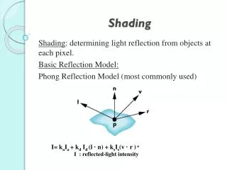
Introduction • Affine transformations help us to place objects into a scene. • Before creating images of these objects, we’ll look at models for how light interacts with their surfaces. • Such a model is called a shading model. • Other names: • Lighting model • Light reflection model • Local illumination model • Reflectance model • BRDF University of Texas at Austin CS384G - Computer Graphics Fall 2010 Don Fussell 3
An abundance of photons • Properly determining the right color is really hard. • Look around the room. Each light source has different characteristics. Trillions of photons are pouring out every second. • These photons can: • interact with the atmosphere, or with things in the atmosphere • strike a surface and • be absorbed • be reflected (scattered) • cause fluorescence or phosphorescence. • interact in a wavelength-dependent manner • generally bounce around and around University of Texas at Austin CS384G - Computer Graphics Fall 2010 Don Fussell 4
Break problem into two parts • Part 1: What happens when photons interact with a particular point on a surface? • “Local illumination model” • Part 2: How do photons bounce between surfaces? And, what is the final result of all of this bouncing? • “Global illumination model” • Today we’re going to focus on Part 1. University of Texas at Austin CS384G - Computer Graphics Fall 2010 Don Fussell 5
Strategy for today • We’re going to build up to an approximation of reality called the Phong illumination model. • It has the following characteristics: • not physically based • gives a first-order approximation to physical light reflection • very fast • widely used • We will assume local illumination, i.e., light goes: light source -> surface -> viewer. • No interreflections, no shadows. University of Texas at Austin CS384G - Computer Graphics Fall 2010 Don Fussell 6
Setup… • Given: • a point P on a surface visible through pixel p • The normal N at P • The lighting direction, L,and intensity, Il,at P • The viewing direction, V, at P • The shading coefficients(material properties) at P • Compute the color, I, of pixel p. • Assume that the direction vectors are normalized: University of Texas at Austin CS384G - Computer Graphics Fall 2010 Don Fussell 7
Iteration zero • The simplest thing you can do is… • Assign each polygon a single color: where • I is the resulting intensity • keis the emissivity or intrinsic shade associated with the object • This has some special-purpose uses, but not really good for drawing a scene. • [Note: ke is omitted in Watt.] University of Texas at Austin CS384G - Computer Graphics Fall 2010 Don Fussell 8
Iteration one • Let’s make the color at least dependent on the overall quantity of light available in the scene: • ka is the ambient reflection coefficient. • really the reflectance of ambient light • “ambient” light is assumed to be equal in all directions • Ia is the ambient intensity. • Physically, what is “ambient” light? University of Texas at Austin CS384G - Computer Graphics Fall 2010 Don Fussell 9
Wavelength dependence • Really, ke, ka, and Ia are functions over all wavelengths . • Ideally, we would do the calculation on these functions. We would start with: • then we would find good RGB values to represent the spectrum I(). • Traditionally, though, ke, ka and Ia are represented as RGB triples, and the computation is performed on each color channel separately: University of Texas at Austin CS384G - Computer Graphics Fall 2010 Don Fussell 10
Diffuse reflectors • Diffuse reflection occurs from dull, matte surfaces, like latex paint, or chalk. • These diffuse or Lambertian reflectors reradiate light equally in all directions. • Picture a rough surface with lots of tiny microfacets. University of Texas at Austin CS384G - Computer Graphics Fall 2010 Don Fussell 11
Diffuse reflectors • …or picture a surface with little pigment particles embedded beneath the surface (neglect reflection at the surface for the moment): • The microfacets and pigments distribute light rays in all directions. • Embedded pigments are responsible for the coloration of diffusely reflected light in plastics and paints. • Note: the figures above are intuitive, but not strictly (physically) correct. University of Texas at Austin CS384G - Computer Graphics Fall 2010 Don Fussell 12
Diffuse reflectors, cont. • The reflected intensity from a diffuse surface does not depend on the direction of the viewer. The incoming light, though, does depend on the direction of the light source: University of Texas at Austin CS384G - Computer Graphics Fall 2010 Don Fussell 13
Iteration two • The incoming energy is proportional to cos(), giving the diffuse reflection equations: where: • kd is the diffuse reflection coefficient • Il is the intensity of the light source • N is the normal to the surface (unit vector) • L is the direction to the light source (unit vector) • (x)+ means max {0, x} [Note: Watt uses Ii instead of Il.] University of Texas at Austin CS384G - Computer Graphics Fall 2010 Don Fussell 14
Specular reflection • Specular reflection accounts for the highlight that you see on some objects. • It is particularly important for smooth, shiny surfaces, such as: • metal • polished stone • plastics • apples • skin • Properties: • Specular reflection depends on the viewing direction V. • For non-metals, the color is determined solely by the color of the light. • For metals, the color may be altered (e.g., brass) University of Texas at Austin CS384G - Computer Graphics Fall 2010 Don Fussell 15
Specular reflection “derivation” • For a perfect mirror reflector, light is reflected about N, so • For a near-perfect reflector, you might expect the highlight to fall off quickly with increasing angle . • Also known as: • “rough specular” reflection • “directional diffuse” reflection • “glossy” reflection University of Texas at Austin CS384G - Computer Graphics Fall 2010 Don Fussell 16
Derivation, cont. • One way to get this effect is to take (R·V), raised to a power ns. • As ns gets larger, • the dropoff becomes {more,less} gradual • gives a {larger,smaller} highlight • simulates a {more,less} mirror-like surface University of Texas at Austin CS384G - Computer Graphics Fall 2010 Don Fussell 17
Iteration three • The next update to the Phong shading model is then: where: • ks is the specular reflection coefficient • ns is the specular exponent or shininess • R is the reflection of the light about the normal (unit vector) • V is viewing direction (unit vector) [Note: Watt uses n instead of ns.] University of Texas at Austin CS384G - Computer Graphics Fall 2010 Don Fussell 18
What is incoming light intensity? So far we’ve just been consideringwhat happens at the surface itself.How does incoming light intensitychange as light moves further away? University of Texas at Austin CS384G - Computer Graphics Fall 2010 Don Fussell 19
Intensity drop-off with distance • OpenGL supports different kinds of lights: point, directional, and spot. • For point light sources, the laws of physics state that the intensity of a point light source must drop off inversely with the square of the distance. • We can incorporate this effect by multiplying I by 1/d2. • Sometimes, this distance-squared dropoff is considered too “harsh.” A common alternative is: with user-supplied constants for a, b, and c. [Note: not discussed in Watt.] University of Texas at Austin CS384G - Computer Graphics Fall 2010 Don Fussell 20
Iteration four • Since light is additive, we can handle multiple lights by taking the sum over every light. • Our equation is now: • This is the Phong illumination model. University of Texas at Austin CS384G - Computer Graphics Fall 2010 Don Fussell 21
Choosing the parameters • Experiment with different parameter settings. To get you started, here are a few suggestions: • Try ns in the range [0,100] • Try ka + kd + ks < 1 • Use a small ka (~0.1) University of Texas at Austin CS384G - Computer Graphics Fall 2010 Don Fussell 22
BRDF • The Phong illumination model is really a function that maps light from incoming (light) directions to outgoing (viewing) directions: • This function is called the Bi-directional Reflectance Distribution Function (BRDF). • Here’s a plot with win held constant: • Physically valid BRDF’s obey Helmholtz reciprocity: and should conserve energy (no light amplification). University of Texas at Austin CS384G - Computer Graphics Fall 2010 Don Fussell 23
Phong BRDF How do we express Phong model usingexplicit BRDF? University of Texas at Austin CS384G - Computer Graphics Fall 2010 Don Fussell 24
More sophisticated BRDF’s Cook and Torrance, 1982 Westin, Arvo, Torrance 1992 University of Texas at Austin CS384G - Computer Graphics Fall 2010 Don Fussell 25
Summary • Local vs. Global Illumination Models • Local Illumination Models: - Phong – Physically inspired, but not truly physically correct. - Arbitrary BRDFs • In applying the Phong model, we assumedunshadowed “point” light sources. University of Texas at Austin CS384G - Computer Graphics Fall 2010 Don Fussell 26
Next time: Ray tracing • Topics: How do we model the transport of light within the scene? How do we determine which surfaces are visible from the eye, or shadowed from a light? • Read: • Watt, sections 1.3-1.4, 12.1-12.5.1. • T. Whitted. An improved illumination model for shaded display. Communications of the ACM 23(6), 343-349, 1980.[Course reader, pp. 211-217] • Optional: • A. Glassner. An Introduction to Ray Tracing. Academic Press, 1989.[In the graphics research lab, ACES 2.102] • K. Turkowski, “Properties of Surface Normal Transformations,” Graphics Gems, 1990, pp. 539-547. [Course reader pp. 218-226] University of Texas at Austin CS384G - Computer Graphics Fall 2010 Don Fussell 27