Download
1 / 55
560 likes | 797 Views
CSC 2141 Introduction to Computer Graphics. Shading. Circle or sphere?. Why we need shading. Suppose we build a model of a sphere using many polygons and color it with glColor . We get something like But we want. Shading.

E N D
CSC 2141 Introduction to Computer Graphics Shading
Why we need shading • Suppose we build a model of a sphere using many polygons and color it with glColor. We get something like • But we want
Shading • Without shading images look flat: fail to show the 3D nature of the model • This appearance is a consequence of our unnatural assumption that each surface is lit such that it appears to the viewer in a single color.
Shading • In reality: when we look at a photograph of a sphere we see different shades of color • These give 2D images the appearance of 3D • Light-material interactions cause each point to have a different shade • So, we will begin developing models of light sources and the most common light-material interactions
Light propagation in the scene • Light is emitted from light sources • Strikes and illuminates objects in the scene • Interacts with object surfaces depending on surface characteristics • Being absorbed all or partially by some objects • Being reflected from or refracted through surfaces • Some light rays eventually enter our eyes • Some leave the scene—no contribution to what we see
Lighting Models • Global illumination models • Simulate this complex interaction of light and objects • Reflections, refractions, shadows are realistic looking • Computationally expensive! • In computer graphics, especially real time graphics, we are happy if things “look right”
Lighting Models • Local illumination models • Shade of a point is calculated independent from other surfaces, and only depend on • locations and properties of light sources • Material properties of surfaces • Local geometry of the surface • Adapted by most commercial interactive graphics systems due to speed concerns • OpenGL uses a local illumination model • There are many techniques for faking the global effects like shadows, reflections..
Light • A large number photons being emitted continuously from each light source • Each photon has an associated color • model color as a triple of red, green, blue components • Intensity of light: number of photons passing through a fixed area over a fixed amount of time • Assuming atmosphere is a vacuum, photons travel in straight lines until hitting a surface • Then, one of three things could happen:
Pure reflection specular reflection diffuse reflection 1. Reflection • Specular reflection: light is reflected in a narrow range of angles close to the angle of reflection. • Smooth surfaces, shiny appearance. • E.g. highly polished metal and shiny plastics. • Pure/perfect reflection: Angle of incidence = angle of reflection. Perfect mirror-like reflectors.
Pure reflection specular reflection diffuse reflection 1. Reflection • Diffuse reflection: Reflected light is scattered in all directions • e.g. walls planted with matte or flat paint. • Surface is rough at the microscopic level • Perfect diffuse: equally in all directions
2. Absorption • Light absorbed into the surface: dissipates in the form of heat energy. • If under white light, an objects looks green • red and blue components are absorbed • Green component is reflected
3. Transmission • Photon passes through the surface • Pure transmission: perfectly transparent objects like glass • Translucent transmission: pass through with a significant amount of scattering, e.g. human skin, thin piece of tissue paper.
Where does light originate from? • Light Sources: light emitting objects. • What specifies a light source • position • direction • intensity
Light sources • In reality: • Many sizes, shapes • Emit light in varying intensities according to direction. • Total contribution of the source to lit surface can be obtained through integrating over the surface of the source
Light sources • We need a simpler model! • OpenGL assumes each light source is a point. • Recall: Energy emitted is modeled as an RGB triple • Denoted by a vector • We will not concern ourselves with units of measurement.
Four basic types of sources • Ambient Light • Point Sources • Spotlights • Distant light sources
1. Ambient Light • Recall: local illumination models ignore indirect lighting due to reflections from other objects. • Causes points in shadow to appear totally black! • We need to compensate for the indirect light that is ignored • Add some uniform light to the scene. • Does not originate from any one location. Like heat, scattered in all locations and directions. • Characterized by an intensity identical at every point in the scene.
2. Point Sources • Emits light equally in all directions with intensity
Point Sources • Widely used due to simplicity. • Scenes rendered with only point sources tend to have high contrast • Too dark or too bright • In the real world, it is the large size of most light sources that contributes to softer scenes.
Q n n l l P P2 l n P3 Point sources: Visibility • A point P is illuminated by a point source at Q only if the line segment does not intersect any other object. • Requires testing intersections : Expensive! Not Local! • OpenGL simply tests whether P is facing towards Q. • n : normal vector at P directed outwards from the object’s interior. • l : light vector pointing from P to Q, that is, l = Q - P
Q n n l l P P2 l n P3 • P: illuminated • P2: illuminated • P3: not illuminated • How can OpenGL do the test (is P facing towards the light source at Q) using n and l?
Q n n l l P P2 l n P3 • P is illuminated by Q • If and only if the angle between n and l is less than 90 • i.e. The dot product of n and l is positive, that is, n.l > 0
Point Sources: Attenuation • Intensity of illumination decreases as the distance to the light source increases. • Physics tells us: intensity falls off as the inverse square of the distance. • Intensity at point P reaching from light source Q:
Attenuation • In local illumination models (thus, in OpenGL) this is too much attenuation: too dim • since indirect lighting is ignored. • Instead OpenGL uses: • Default, a=1, b=0, c=0 • Try and see till you get the best looking image!
3.Spotlights • Spotlights are characterized by a narrow range of angles through which light is emitted. • A spotlight can be constructed from a point source by limiting the direction of emission within a cone. • Intensity is strongest along a given direction: the axis of the cone. • Intensity drops off according to the angle from the axis of the cone.
4.Distant Light Sources • If the light source is far from the surface, the direction of light is uniform across the entire surface (the sun). • Equivalent to a source that illuminates objects with parallel rays of light. • In OpenGL, set point source location as [x, y, z, 0] to specify a distant light source
Distant light sources • Graphics systems can carry out rendering calculations more efficiently for distant light sources than for near ones. • n.l is computed once for all points on a flat polygon!
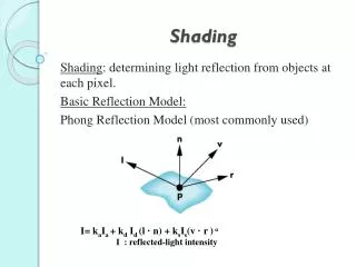
Phong Reflection Model • We need to consider how light reflects off due to object’s surface properties • We will assume all our objects are opaque. • Phong Reflection Model models surface reflection as a combination of • emission, • ambient reflection, • diffuse reflection, • specular reflection. • OpenGL uses a slightly modified Phong Model
Let L denote the intensity of the light source • OpenGL lets us break this into ambient, diffuse and specular components • e.g. RGB representation of the diffuse component
Separating diffuse and specular components?? • OpenGL lets you turn on/off a light sources ability to generate diffuse or specular reflection! • Do you see something strange with this? • Set diffuse = specular usually. • Separate ambient is understandable? • Consider white light in a red room • In reality, the reflection from the wall add a red/pink ambient component • We can model this by a light with white diffuse and specular, but red ambient component
Steps in OpenGL shading • Enable shading and select model • Specify lights • Specify material properties • Specify normals
Enabling Shading • Shading calculations are enabled by • glEnable(GL_LIGHTING) • Once lighting is enabled, glColor() ignored • Must enable each light source individually (upto 8 sources may be created) • glEnable(GL_LIGHTi) i=0,1…..7
In initialization: set lighting model • Can choose light model parameters • glLightModeli(parameter, GL_TRUE) • GL_LIGHT_MODEL_TWO_SIDED shades both sides of polygons independently • glLightModelfv(GL_LIGHT_MODEL_AMBIENT,rgba) • If ambient light depends on color of light sources, a red light in a white room will cause a red ambient term that disappears when the light is turned off • OpenGL also allows a global ambient term
In initialization: set shading model • glShadeModel(GL_SMOOTH) • Vertex shades are blended to shade a polygon • glShadeModel(GL_FLAT) • Shade of the first vertex is used to shade the polygon.
Defining a Point Light Source • For each light source, we can set an RGBA for the diffuse, specular, and ambient components, and we set the position—set diffuse=specular. GLfloat diffuse0[]={1.0, 0.0, 0.0, 1.0}; GLfloat ambient0[]={1.0, 0.0, 0.0, 1.0}; GLfloat specular0[]={1.0, 0.0, 0.0, 1.0}; Glfloat light0_pos[]={1.0, 2.0, 3,0, 1.0}; glEnable(GL_LIGHTING); glEnable(GL_LIGHT0); glLightfv(GL_LIGHT0, GL_POSITION, light0_pos); glLightfv(GL_LIGHT0, GL_AMBIENT, ambient0); glLightfv(GL_LIGHT0, GL_DIFFUSE, diffuse0); glLightfv(GL_LIGHT0, GL_SPECULAR, specular0);
Distance and Direction • The source colors are specified in RGBA • Set A=1.0 for now (all objects are opaque) • The position is given in homogeneous coordinates • If w =1.0, we are specifying a finite location • If w =0.0, we are specifying a distant source with the given direction vector • The coefficients in the distance terms are by default a=1.0 (constant terms), b=c=0.0 (linear and quadratic terms). You may change by a= 0.80; b=1.0; c =1.0; glLightf(GL_LIGHT0, GL_CONSTANT_ATTENUATION, a); glLightf(GL_LIGHT0, GL_LINEAR_ATTENUATION, b); glLightf(GL_LIGHT0, GL_QUADRATIC_ATTENUATION,c);
Default Lights • No ambient light for any light • Diffuse and specular • For light source 0: (1,1,1,1) • For other light sources : (0, 0, 0, 1) • Default value of position: • (0,0,1,0) • at infinity
f q -q Spotlights • Use glLightf(v) to set • Direction GL_SPOT_DIRECTION • Default: negative Z direction • Cutoff GL_SPOT_CUTOFF • Default: 180 • Attenuation GL_SPOT_EXPONENT (give a positive value to have light drop off exponentially as we go away from the center) GLfloat d[]={1.0, 0.0, 0.0}; glLightfv(GL_LIGHT0, GL_SPOT_DIRECTION, d);
Moving Light Sources • Light sources are geometric objects whose positions or directions are affected by the model-view matrix • Depending on where we place the position (direction) setting function, we can • Move the light source(s) with the object(s) • Fix the object(s) and move the light source(s) • Fix the light source(s) and move the object(s) • Move the light source(s) and object(s) independently
Light position • How do I keep light position fixed relative to the camera (How can I make a headlight attached to the camera?) • Set light position in your init() when modelview matrix is identity, e.g. set it to (0,0,0) • We do not want the view transform (the one set by gluLookAt) applied to light position in this case. • How do I keep light position fixed relative to the scene? • Set light position after gluLookAt at the start of each frame
Material properties • An objects color determines how much of a given intensity is reflected • Let denote object’s color • (all components are in [0,1]) • Think of as the fraction of red light reflected • E.g., if 0, no red light is reflected.
Light-surface interaction • When light of intensity L hits an object of color C, the amount of reflected light is • Beware: This is a component by component multiplication, not a vector multiplication or dot product! • L=[1,1,1] and C=[1,0,0] LC = [1,0,0] • L=[0,0,1] and C = [1,0,0] LC = [0,0,0] • What color will the object appear?
Separating ambient, diffuse, specular • In OpenGL, rather than a single color, we can specify amount of reflection for each type of illumination • For example, it allows you to specify an object, that can reflect only red ambient light, and only blue diffuse light!!! • Common to set (color of light) why?
Specifying material properties in OpenGL • When lighting is in effect • Do not use glColor(…) • Instead we will set material properties, and OpenGL will compute the shading based on those. • Surface properties are assigned to vertices---not to faces! • Color is computed for each vertex • Interpolated over the polygon (smooth shading), or color of first vertex is used (flat shading)
Front and Back Faces • Recall: Order of vertices determine which face is front. • The default is shade only front faces • works correctly for convex objects • If we set two sided lighting, OpenGL will shade both sides of a surface glLightModeli(GL_LIGHT_MODEL_TWO_SIDED, GL_TRUE); • Each side can have its own properties back faces not visible back faces visible
Material Properties • Material properties are also part of the OpenGL state and match the terms in the modified Phong model • Set by glMaterialfv(face, pname, pvalue) • face: GL_FRONT, GL_BACK, GL_FRONT_AND_BACK • GL_SHININESS: larger it is, smaller the highlight GLfloat ambient[] = {0.2, 0.2, 0.2, 1.0}; GLfloat diffuse[] = {1.0, 0.8, 0.0, 1.0}; GLfloat specular[] = {1.0, 1.0, 1.0, 1.0}; GLfloat shine = 100.0 glMaterialfv(GL_FRONT, GL_AMBIENT, ambient); glMaterialfv(GL_FRONT, GL_DIFFUSE, diffuse); glMaterialfv(GL_FRONT, GL_SPECULAR, specular); glMaterialf(GL_FRONT, GL_SHININESS, shine);
Emissive Term • We can simulate a light source in OpenGL by giving a material an emissive component • This is useful if you want a light source to appear in your image. • It is unaffected by any light source • Object appears as glowing but will not in fact emit any light—does not lit other objects. GLfloat emission[] = 0.0, 0.3, 0.3, 1.0); glMaterialf(GL_FRONT, GL_EMISSION, emission);
Transparency • Material properties are specified as RGBA values • The A value can be used to make the surface translucent • The default is that all surfaces are opaque regardless of A • Later we will enable blending and use this feature