Download
1 / 56
560 likes | 863 Views
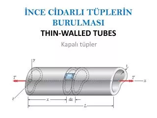
Understanding and classifying local, distortional and global buckling in open thin-walled members by: B.W. Schafer and S. Ádány. SSRC Annual Stability Conference Montreal, Canada April 6, 2005. Motivation and challenges Modal definitions based on mechanics Implementation Examples.

E N D
Understanding and classifying local, distortional and global buckling in open thin-walled membersby: B.W. Schafer and S. Ádány SSRC Annual Stability Conference Montreal, Canada April 6, 2005
Motivation and challenges • Modal definitions based on mechanics • Implementation • Examples
What are the buckling modes? • member or global buckling • plate or local buckling • other cross-section buckling modes? • distortional buckling? • stiffener buckling?
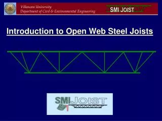
Buckling solutions by the finite strip method • Discretize any thin-walled cross-section that is regular along its length • The cross-section “strips” are governed by simple mechanics • membrane: plane stress • bending: thin plate theory • Development similar to FE • “All” modes are captured y
local buckling distortional buckling lateral-torsional buckling Typical modes in a thin-walled beam Mcr Lcr
What mode is it? ? Local LTB
Are our definitions workable? • Distortional buckling. A mode of buckling involving change in cross-sectional shape, excluding local buckling • Not much better than “you know it when you see it” • definition from the Australian/New Zealand CFS standard, • the North American CFS Spec., and the recently agreed • upon joint AISC/AISI terminology
We can’t effectively use FEM • We “need” FEM methods to solve the type of general stability problems people want to solve today • tool of first choice • general boundary conditions • handles changes along the length, e.g., holes in the section 30 nodes in a cross-section 100 nodes along the length 5 DOF elements 15,000 DOF 15,000 buckling modes, oy! • Modal identification in FEM is a disaster
Generalized Beam Theory (GBT) • GBT is an enriched beam element that performs its solution in a modal basis instead of the usual nodal DOF basis, i.e., the modes are the DOF • GBT begins with a traditional beam element and then adds “modes” to the deformation field, first Vlasov warping, then modes with more general warping distributions, and finally plate like modes within flat portions of the section • GBT was first developed by Schardt (1989) then extended by Davies et al. (1994), and more recently by Camotim and Silvestre (2002, ...)
Generalized Beam Theory • Advantages • modes look “right” • can focus on individual modes or subsets of modes • can identify modes within a more general GBT analysis • Disadvantages • development is unconventional/non-trivial, results in the mechanics being partially obscured • not widely available for use in programs • Extension to general purpose FE awkward • We seek to identify the key mechanical assumptions of GBT and then implement in, FSM, FEM, to enable these methods to perform GBT-like “modal” solutions.
Globalmodes are those deformation patterns that satisfy all three criteria. #1 #2 #3
#1 membrane strains: gxy = 0, membrane shear strains are zero, ex = 0, membrane transverse strains are zero, and v = f(x), long. displacements are linear in x within an element. #1 #2 #3
#2 warping: ey 0, longitudinal membrane strains/displacements are non-zero along the length. #1 #2 #3
#3 transverse flexure: ky = 0, no flexure in the transverse direction. (cross-section remains rigid!) #1 #2 #3
Distortionalmodes are those deformation patterns that satisfy criteria #1 and #2, but do not satisfy criterion #3 (i.e., transverse flexure occurs). #1 #2 #3
Localmodes are those deformation patterns that satisfy criterion #1, but do not satisfy criterion #2 (i.e., no longitudinal warping occurs) while criterion #3 is irrelevant. #1 #2 #3
Othermodes(membrane modes ) do not satisfy criterion #1. Note, other modes typically do not exist in GBT, but must exist in FSM or FEM due to the inclusion of DOF for the membrane. #1 #2 #3
so a GBT criterion is or therefore Constrained deformation fields FSM membrane disp. fields:
impact of constrained deformation field general FSM constrained FSM
Modal decomposition • Begin with our standard stability (eigen) problem • Now introduce a set of constraints consistent with a desired modal definition, this is embodied in R • Pre-multiply by RT and we create a new, reduced stability problem that is in a space with restricted degree of freedom, if we choose R appropriately we can reduce down to as little as one “modal” DOF
lipped channel in compression • “typical” CFS section • Buckling modes include • local, • distortional, and • global • Distortional mode is indistinct in a classical FSM analysis 50mm 20mm 200mm P t=1.5mm
I-beam cross-section • textbook I-beam • Buckling modes include • local (FLB, WLB), • distortional?, and • global (LTB) • If the flange/web juncture translates is it distortional? 80mm tf=10mm 200mm M tw=2mm
concluding thoughts • Cross-section buckling modes are integral to understanding thin-walled members • Current methods fail to provide adequate solutions • Inspired by GBT, mechanics-based definitions of the modes are possible • Formal modal definitions enable • Modal decomposition (focus on a given mode) • Modal identification (figure out what you have) within conventional numerical methods, FSM, FEM.. • The ability to “turn on” or “turn off” certain mechanical behavior within an analysis can provide unique insights • Much work remains, and definitions are not perfect
acknowledgments • Thomas Cholnoky Foundation • Hungarian Scientific Research Fund • U.S., National Science Foundation
? P varying lip angle in a lipped channel • lip angle from 0 to 90º • Where is the local – distortional transition? 120mm q 10mm 200mm t=1mm
classical finite strip solution q q = 0º = 18º = 36º = 54º = 72º = 90º Local? Distortional? L=700mm, q=54-90º Local? Distortional? L=170mm, q=0-36º
q = 0º = 18º = 36º = 54º = 72º = 90º q=0 q=18º
? What mode is it?
lipped channel with a web stiffener • modified CFS section • Buckling modes include • local, • “2” distortional, and • global • Distortional mode for the web stiffener and edge stiffener? 50mm 20mm 200mm P 20mm x 4.5mm t=1.5mm
Membrane (plane stress) FSM Ke = Kem + Keb
Thin plate bending FSM Ke = Kem + Keb
Membrane (plane stress) FSM Ke = Kem + Keb
FSM Solution • Ke • Kg • Eigen solution • FSM has all the cross-section modes in there with just a simple plate bending and membrane strip