Download
1 / 29
1.72k likes | 4.99k Views
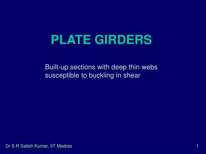
PLATE GIRDERS. Built-up sections with deep thin webs susceptible to buckling in shear. flange plates. web plate. ITS. BS. LS. Types of Plate Girders. Unstiffened Plate Girder Transversely Stiffened Plate Girder Transversely and Longitudinally Stiffened Plate Girder.

E N D
PLATE GIRDERS Built-up sections with deep thin webs susceptible to buckling in shear Dr S R Satish Kumar, IIT Madras
flange plates web plate ITS BS LS Types of Plate Girders • Unstiffened Plate Girder • Transversely Stiffened Plate Girder • Transversely and Longitudinally Stiffened Plate Girder Dr S R Satish Kumar, IIT Madras
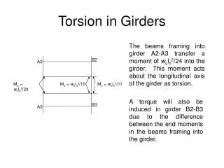
SHEAR RESISTANCE OF STIFFENED GIRDER Shear resistance of a web • Pre-buckling behaviour (Stage 1) • Requirements of equilibrium in an element inside a square web plate subject to a shear stress result in generation of complementary shear stresses • This results in element being subjected to principal compression along one diagonaland tension along the other Dr S R Satish Kumar, IIT Madras
q B A q q E 45o D C Unbuckled Shear panel q Shear resistance of a web - 1 Dr S R Satish Kumar, IIT Madras
cr BUCKLING OF WEBPLATES IN SHEAR Shear buckling of a plate Dr S R Satish Kumar, IIT Madras
Shear resistance of a web - 2 • As the applied loading is incrementally enhanced, plate will buckle along direction of compressive diagonal - corresponding shear stress in plate is“critical shear stress” • Critical shear stress in such a case is given by • Boundary conditions assumed to be simply supported Dr S R Satish Kumar, IIT Madras
d c Shear resistance of a web - 3 • shear buckling coefficient (ks) given by Dr S R Satish Kumar, IIT Madras
Post buckled behaviour (Stage 2) • Compression diagonal is unable to resist any more loading beyond elastic critical stress • Any further increase in shear load is supported by a tensile membrane field, anchored to top and bottom flanges and adjacent stiffener members on either side of web • Total state of stress in web plate may be obtained by superimposing post-buckled membrane tensile stresses upon critical shear stress Dr S R Satish Kumar, IIT Madras
Anchoring of Tension Field Post buckled behaviour - 1 Dr S R Satish Kumar, IIT Madras
Tension field action Dr S R Satish Kumar, IIT Madras
Collapse behaviour (Stage 3) • When load is further increased, tensile membrane stress continues to exert an increasing pull on flanges • Eventually resultant stress obtained by combining the buckling stress and membrane stress reaches yield value for web - can be determined by Von-Mises yield criterion Dr S R Satish Kumar, IIT Madras
Tensile membrane stress at yield Collapse of the panel Collapse behaviour - 1 Dr S R Satish Kumar, IIT Madras
Three phases of tension field action Pre-buckling post-buckling collapse Dr S R Satish Kumar, IIT Madras
ULTIMATE BEHAVIOUR OF TRANSVERSE WEB STIFFENERS Transverse stiffeners play important role by increasing web buckling stress by supporting tension field after web buckling by preventing tendency of flanges to get pulled towards each other Stiffeners should possess sufficient rigidity to ensure that they remain straight, while restricting buckling to individual web panels 14 Dr S R Satish Kumar, IIT Madras
ULTIMATE BEHAVIOUR OF TRANSVERSE WEB STIFFENERS - 1 Force imposed on transverse stiffeners by tension field 15 Dr S R Satish Kumar, IIT Madras
GENERAL BEHAVIOUR OF LONGITUDINALLY STIFFENED GIRDERS Generally located in compression zones of girder Main function - to increase buckling resistance of web When it is subject predominantly to shear would develop a collapse mechanism, provided stiffeners remained rigid up to failure Once one of sub panels has buckled, post buckling tension field develops over whole depth of web panel and influence of stiffeners may be neglected 16 Dr S R Satish Kumar, IIT Madras
Longitudinal and Transverse stiffeners GENERAL BEHAVIOUR OF LONGITUDINALLY STIFFENED GIRDERS – 1 Dr S R Satish Kumar, IIT Madras
IS 800: 2007 • 8.4 Shear • The factored design shear force, V, in a beam due to external actions shall satisfy • V Vd • Vd = design strength calculated as , Vd = Vn/ γm0 • 8.4.1 The nominal plastic shear resistance under pure shear is given by: Vn = Vp • Av = shear area • Cont… Dr S R Satish Kumar, IIT Madras
IS 800: 2007 • 8.4.2 Resistance to Shear Buckling • for an unstiffened web • for a stiffened web • Simple Post-Critical Method • The nominal shear strength is • Vn = Vcr Vcr = d twb • b = shear stress corresponding to buckling, • b) Tension Field Method • The nominal shear strength is • V n = V tf Dr S R Satish Kumar, IIT Madras
b 0.8 1.25 w 8.4.2.2 Shear Buckling Design Methods a) Simple Post-Critical Method -The nominal shear strength is Vn = Vcr Vcr = d twb b = shear stress corresponding to buckling, determined as follows: a) When w < 0.8 b) When 0.8 < w< 1.25 c) When w1.25 b =0.9 fyw/(3w2) Cont… Dr S R Satish Kumar, IIT Madras
IS 800: 2007 λw = non -dimensional web slenderness ratio for shear buckling stress, given by The elastic critical shear stress of the web, cr is given by: kv = 5.35 when transverse stiffeners are provided only at supports = 4.0 +5.35 /(c/d)2 for c/d < 1.0 = 5.35+4.0 /(c/d)2 for c/d 1.0 Cont… Dr S R Satish Kumar, IIT Madras
sc wtf st c IS 800: 2007 • b) Tension Field Method - the nominal shear resistance, Vn, should be Vn=Vtf • Vnp • fv = yield strength of the tension field obtained from • =1.5b sin 2 • = inclination of the tension field • The width of the tension field, wtf, is given by: • wtf = d cos – (c-sc-st) sin Dr S R Satish Kumar, IIT Madras
IS 800: 2007 • 8.6 Design of Beams and Plate Girders with Solid Webs • 8.6.1 Minimum Web Thickness • 8.6.1.1 Serviceability Requirement • a) when transverse stiffeners are not provided • (web connection by flanges along both longitudinal edges) • (web connection by flanges along one longitudinal edge only) • b) when transverse stiffeners only are provided; • when c d • ii) when 0.74 d<c < d • iii) when c < 0.74 d • Cont… Dr S R Satish Kumar, IIT Madras
c) when transverse and longitudinal stiffeners are provided at one level only • (0.1 d from compression flange) • i) when c > d • ii) when 0.74 d<c < d • iii) when c < 0.74 d • d) when a second longitudinal stiffener (located at neutral axis is provided ) • Cont… Dr S R Satish Kumar, IIT Madras
Design Procedure Initial Sizing • Taking L/d as 15, calculate min. d and provide suitably • Afreqrd. = BM/ (fy/mo)d ; using bf = 0.3d select flange plate Also calculate Nf = axial force in the flange • Check that flange criteria gives a plastic section b = (bf – tw)/2 and b/ tf < 7.9 • Web thickness for serviceability 67 < d/ tw < 200 choose such that tw > d/200 • Check for flange buckling into web Assuming c >1.5d , d/ tw < 3452 Dr S R Satish Kumar, IIT Madras
Design Procedure • Check for shear capacity of web V < Vd = Vn/ mo; Vn = A (fyw /3) or Vcr • Check for calculating resistance to shear buckling d/ tw > 67 (kv/5.35) use kv for c/d > 1 8) Simple post-critical method Vcr = d twb where b = (w) and w = (cr) 9) If V < Vcr/ mo then safe else tension field calculation reqrd. 10) Vn = Vtf = (fv and ); also calculate Mfv = (Nf) If V < Vn/ mo safe ! else revise design Dr S R Satish Kumar, IIT Madras
IS 800: 2007 Design Procedure • 8.7 Stiffener design • a) Intermediate Transverse Web Stiffener To improve the buckling strength of slender web due to shear. • b) Load Carrying Stiffener To prevent local buckling of the web due to concentrated loading. • c) Bearing Stiffener To prevent local crushing of the web due to concentrated loading . • d) Torsion Stiffener To provide torsional restraint to beams and girders at supports. • e) Diagonal Stiffener To provide local reinforcement to a web under shear and bearing. • f) Tension StiffenerTo transmit tensile forces applied to a web through a flange. Dr S R Satish Kumar, IIT Madras
bs tq Design Procedure 11) End panel design – check as a beam between flanges Rtf = Hq/2 Av = c t and Vtf = Av (fy/3) > Rtf 12) Mtf = Hqd/10 MR = tc3/12*fyd / (c/2) > Mtf 13) Intermediate Transverse Stiffener Design i) decide to provide stiffener on one side or both sides ii) choose tq > tw ; outstand bs < 14tq also < b 14) check for minimum stiffness Cl.8.7.2.4 p91 for c = 1.5d, c > 2 d giving I prov. = (bs-tw/2)3 tq/12 > 0.75dtw3 Rtf c Dr S R Satish Kumar, IIT Madras
bs tq Design Procedure 15) Check for Buckling Cl.8.7.2.5 p91 Stiffener force, Fq = V - Vcr/mo Fqd Buckling Resist. Pq with 20tw on either side Cl.8.7.1.5 p90 Calculate Ixx and A, rxx = (Ixx/A) Leff = 0.7d, = Leff/rxx, Find fc Pq = fc A > Fq 16) Connection to web Cl.8.7.2.6 p92 shear = tw2 / 8bs kN/mm choose appropriate weld size 19) Check for Intermediate Stiffener under Load Cl.8.7.2.5 p91 Dr S R Satish Kumar, IIT Madras