Download
1 / 32
320 likes | 343 Views
Overview and tools used for operational improvements in beam stability since machine commissioning, focusing on feedback systems, motion sources, and reproducibility enhancements.

E N D
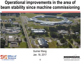
Operational improvements in the area of beam stability since machine commissioning Guimei Wang Jan. 18, 2017
Outline • SR overview • Beam stability monitor tools • Beam stability feedback systems • Machine reproducibility improvements • Beam short term motion sources and stability • Beam long term drift: RF frequency feedback • Beam motion from transition • ID gap change • Top off injection • Summary
SR Overview • 3 GeV, 792 m Storage Ring • 500 mA beam current with 1 nm-rad horizontal and 8 pm-rad vertical emittance. • Beam sizes at source points are ~100 µm/3 µm • High beam stability in position (<10% of rms size) and angle (<10% of rms divergence) • 1080 bunches in 1320 RF buckets, 3 hrs lifetime • Top off injection for stable intensity (±0.5% variation) • 30 cells DBA • The storage ring commissioning started in later March 2014 • Beamlines operation started in Feb. 2015 • 23 beamlines operating/commissioning (IVUs, EPUs, DWs, 3PWs, BM) • Beam current: ops 350 mA and study 400 mA
One super-period SR Lattice function C F C C F C C C F • Each cell includes 6 DC correctors (H+V), 3 Fast correctors (H+V), Arc BPMs (6) + ID BPMs (2~4), FE photon BPMs • Feedback systems: SOFB, FOFB, RF frequency feedback, local photon feedback One cell elements
BPM system • BPM: in house development with TBT, 10 kHz and 10 Hz capability for x, y and intensity • High resolution verified with beam: 200 nm in 10 kHz, 1 µm in TBT (single bunch fill) • TBT for injection & fast kick beam studies (routine lattice correction), Post mortem data to analysis beam loss, beam motion glitch… • FA for fast orbit feedback & interlocks; SA for orbit measurements and slow orbit feedback BPM FA/TBT resolution measurement BPM slicer for beam position loss monitor Resolution ~ 1/sqrt(38) ~ 200 nm resolution achieved BPMs TBT data for lattice correction Sub-um resolution for TbT data 1 mA single bunch More details in Danny’s talk
Beam stability monitor tools • BPM 10 Hz data x, y, intensity: monitor long term beam drift (secs to days), low frequency spectrum (<1 Hz), lifetime • BPM 10 kHz data x, y: monitor short term beam stability (ms to secs), high frequency spectrum (Hz to kHz), dedicate BPM for online beam motion spectrum monitor trigged at 1 Hz mode Online beam motion spectrum
Beam stability monitor tools Cont’d • Tools to hourly monitor beam motion 10 kHz all BPMs power spectral density peaks amplitude and frequency, daily track machine performance (Refer Boris’s talk) • BPM TBT data for beam fast motion detect: under development Beam fast motion detect Orbit and FC changes during fast motion
Beam stability feedback systems • SOFB: 180 BPMs 10 Hz data + 180 DC correctors (upto 1 mrad) in both X and Y plane (Operation from May 2014) • FOFB (Operation from June 2015 and continuously improved): • X plane: 90 FC correctors + BPMs 10 kHz data (120 arc non-dispersion BPMs + ID BPMs) • Y plane: 90 FC correctors + BPMs 10 kHz data (180 arc BPMs + ID BPMs) • RF frequency feedback: RF frequency + 60 dispersion BPMs 10 Hz data (Operation from Apr. 2017) • ID local bump for source control: local DC correctors + BPMs 10 Hz data • ID local photon feedback: ID corrector coils + FE xBPM 10 Hz data (Oct. 2017, Refer Yuke’s talk)
Machine reproducibility • Setup the magnet cycle sequence: main dipole + trim coils • Optimize magnet cycle: ramping rate + #NO of cycles (48) • Orbit correction/recovery with SOFB: • Converge to 10 mm in short term • ~100 mm difference in long term redefine operation reference orbit, but maintain ID source position with local bump FOFB to recover orbit after beam dump Beam orbit for operation
Orbit correction with SOFB • Correctors local fight small phase advance, a few degree in between • Correctors’ sum strength swings in a large range improved SOFB algorithm by adding the weight of sum strength Corrector strength distribution w/o balance Correctors’ sum strength history 2017 Jan. 2018 Jan.
BBA measurement BBA drift: 2007 Nov. relative to 2016 Feb. BBA • BBAs in x plane change ~100 µm over a year • BBAs in y plane are in negative side with small drift over a year
BPM positon-attenuator dependence • BPM static gain calibration: minimize the positon-attenuator dependence from 50 µm to a few µm
Machine reproducibility Cont’d • Orbit recovery with FOFB after beam dump: improve photon source position reproducibility (<1 µm VS a few µmwith SOFB), simplify orbit recovery process • Shift fast correctors strength to DC correctors • ID local bump: • Dedicated to control ID photon source position and angle • V2: feedback correction BPMs to new value, several iteration to a few µrad difference (BL: required µrad), not compatible with FOFB system running • V3: feedforward correction* , set beam reference orbit and calculated correctors simultaneously, running along with FOFB system • Minimize the correction transition (~ 1µrad, µm) and residual (< µrad) Principle of ID source bump feedforward: corrector delta and bpm reference delta* FOFB to recover orbit after beam dump *L. Emery, et.al, BEAMLINE-CONTROLLED STEERING OF SOURCE-POINT ANGLE AT THE ADVANCED PHOTON SOURCE, NPAC 2016, Chicago
ID local bump correction V2 bump V3 bump • For 30 rad horiz. angle change at C05, V2: Up to 60 m offset & 4 rad angle change, V3: <1 m offset & <1 rad angle change
Beam Short-Term Stability: Horizontal spectrum All 180 BPMs sampled for 10 sec at 10 kHz; orbit feedbacks off Ring-average BPM spectra (psd and integrated) Plenty of spectral features; but integrated levels are very small Booster 60 Hz RF RF cryo? Girder vibration
Beam Short-term Stability: Vertical spectrum Same plot for the vertical Plenty of spectral features; but integrated level is very small 60 Hz (from ?) Booster RF Girder vibration
Beam Short-term Stability: Booster Ramp Booster magnet ramps (mainly BD1) induce 1 Hz orbit noise + harmonics Turning them all off (black curve) eliminates this noise completely This noise is reproducible set booster in sleep mode Or can be taken out by the FOFB.
Beam Short-term Stability: Pinger Pinger AC contactors ON • Uses Matlab Middle Layer by Greg Portmann • Input is any sampled orbit data file, usually FA (10 kHz), or SA (10 Hz) • Most of the 60 Hz noise coming from one single location, s~580 m, Pinger Pinger AC contactors OFF
Dispersive BPM noise is dominated by RF, but it is still small! Recent adjustment of the switching frequency of the RF HVPS to have synchrotron peak in a to “quieter region” i.e. between the switching frequency sub-harmonics (112 kHz/86 modules) Strongest switching frequency lines are down by a factor of ~6 Beam Short-term Stability: RF Noise
Beam Short-term Stability: RF Noise Cont’d The noise is a very small percentage of beam size The noise does not directly affect the (ID) users It cannot be cured by FOFB (frequency too high !) May need to revisit once IR beamlines come online
Beam Short-term Stability with FOFB Power spectrum density Integrated motion
Beam short-term Stability with FOFB Integrated motion along the ring • Beam orbit stability specification: 10% beam size • Horizontal stability: 1% beam size • Vertical stability: ~ 10% beam size
RF Frequency feedback for long term drift BM stability with RF freq. FB • Bending magnet/3PW photon source located at high dispersion location • SR circumference daily change can cause BM photon source ~50 um, which cannot be corrected with FOFB • RF frequency feedback was implemented to suppress beam long term drift • BM source long term stability<10% beam size 10 µm TES bending magnet beamline
Beam motion from transition: ID gap change • The ID gap change will affect the stored beam close orbit due to residual field integral • Treat ID as drift & fit US & DS virtual kick angles that produce measured COD difference • Orbit feedforward system applies opposite kicks at both ends to minimize orbit disturbance outside ID • Issues: beam position dependence and long term drift Residual Orbit Distortion: Feedforward Off vs. On Orbit Diff: Open vs. Closed Gap ID Feedforward drift ON OFF
Beam motion from transition: Top Off Injection 9.5mm Pulse septum 1 2 Kickers 4 3 15 mm 17.5 mm 24.5 mm Stored beam Injected beam TBT Xrms VS injection bucket TBT residual oscillation Original set Fixed bucket Moving bucket
Summary • Powerful BPM system and tools to monitor beam short and long term stability • Improved machine reproducibility: optics (magnets cycling), orbit (SOFB, ID local bump feedforward, FOFB) • Identified motion sources at different frequency and suppressed them • Feedback systems to maintain beam stability • FOFB system suppressed short term high frequency (upto 300 Hz) beam motion and maintained long term stability • RF frequency feedback maintained BMs’ source long term stability • Local photon feedback maintained BMs’ source long term stability (Yuke’s talk) • Beam motion transition from ID gap change: improved with orbit feedforward system need to understand long term drift • Beam motion transition from top off injection: improved with kickers amplitude and timing match further improve requires online waveform adjustment
Acknowledgements • Accelerator Coordination: J. Choi, Y. Hidaka, R. Smith, L. Doom • Accelerator Physics: V. Smalyuk, B. Podobedov, L.H. Yu, X. Yang, W. Guo, Y. Li • Beam Operations group: E. Zitvogel, R. Fliller, M. Santana, G. Weiner, E. Zeitler, R. Rayner, C. Gardner, P. Marino • Controls group: Y. Tian, A. Derbenev, K. Ha • Diagnostics and Instrumentation group: D. Padrazo, W. Cheng, C. Danneil, A. Caracappa • ID group: T. Tanabe, C. Kitegi, J. Rank • Electrical Engineering: G. Ganetis, P. Zuhoski, W. Louie… • Mechanical Engineering group: S. Sharma, M. Loftus, C. Amundsen, C. Spataro, F. Karl… • Mechanical Utilities: J. Gosman… • RF group: J. Rose, F. Gao, J. Cuppolo, J. Culpin, B. Holub, C. Marques • Vacuum group: C. Hetzel…